Structural Analysis
6th Edition
ISBN: 9781337630931
Author: KASSIMALI, Aslam.
Publisher: Cengage,
expand_more
expand_more
format_list_bulleted
Question

Transcribed Image Text:Certainly! Here's the transcription of the image text:
---
**(5) Check if the section is properly designed to resist the max. bending Mu?**

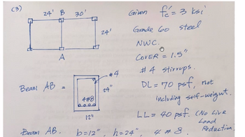
Transcribed Image Text:### Structural Design Example
#### Diagram
The diagram depicts a structural layout with two beams labeled "A" and "B". The span dimensions are:
- **Beam A**: 24 feet
- **Beam B**: 30 feet (both spans are 24 feet in another direction)
#### Specifications
- **Concrete Strength**: \( f'_c = 3 \, \text{ksi} \)
- **Steel Grade**: Grade 60 Steel
- **Concrete Type**: Normal Weight Concrete (NWC)
- **Cover**: 1.5 inches
- **Stirrups**: #4 stirrups
#### Loads
- **Dead Load (DL)**: 70 psf (not including self-weight)
- **Live Load (LL)**: 40 psf (No Live Load Reduction)
#### Beam AB
- Dimensions: \( b = 12'' \), \( h = 24'' \)
- **Reinforcement**:
- \( 4 \# 8 \) bars for the main reinforcement
- #4 stirrups positioned vertically at 24 inches
This illustration and accompanying notes provide important parameters for analyzing and designing beam AB following typical structural engineering practices.
Expert Solution
arrow_forward
Step 1
Check if section is adequate or not?
Step by stepSolved in 3 steps with 2 images

Knowledge Booster
Learn more about
Need a deep-dive on the concept behind this application? Look no further. Learn more about this topic, civil-engineering and related others by exploring similar questions and additional content below.Similar questions
- X Incorrect Three plates are welded together to form the section shown. Dimensions of the cross section are b = 3.6 in., d = 10.8 in., a = 2.3 in., and t= 0.4 in. For a vertical shear force of V = 39 kips, determine the shear flow through the welded surface at B. d В Answer: i 1.283 kip/in.arrow_forwardQ2/ Segments AB and BC of the assembly below are made from 6061-T6 aluminum. If a couple forces P = 5 kip are applied to the lever arm, Determine (a) the reactions at the fixed supports A and C and (b) the shear stress developed at a point located 1 in. from the center-line of the bar at a cross-section close to point A. 2.5 fi 2.5 ft 6 ft 4 in. 4 in.arrow_forwardBy inspection, determine the zero-force members in each truss. Identify the zero-force member by placing an “X” through that member. If you need to do this iteratively, and redraw the truss without the zero-force members you have already found, you may do so.arrow_forward
- From the given trusses below, determine the force in the member DE. (kN) Hint: V = -20.9 kN Note: Use two (2) decimal places in the final answer. G H R P M 1.5 m L к 75 kN 75 kN 9 equal bays at 3.0 m each 3.0 marrow_forwardAssume that the clamp shown has been tightened on wooden planks being glued together until P = 420 N. Determine the stress in A and D Find the location of the neutral axisarrow_forwardStatics - Zero Force Members1. Identify the zero-force members in the truss shown. 2. Redraw the truss without the zero-force members included.arrow_forward
- A snow load transfers the forces shown to the upper joints of the Pratt and Howe roof lattices shown below. Ignoring the horizontal responses on the supports ( \(A x=Ex=0 \)) a) Determine the forces in all members using the joint method. Pratt Roof Truss System: AA A 2 Rods Pull Push CC=5,7 WIDTH (m) x=2 y=3,4 height (m) z=4,2 X 1 BB H 2 y 3 CC G y BB 5 D F X Pratt Roof Truss System SOLUTION: 6 AA E A 4-digit number must be written after the comma. For example 14.7845. Forces (kN) AA=4,2 BB=4,2 Aarrow_forwardHand written and clean writing pleasearrow_forwardFind 5 internal forces of the truss members, Also Find all zero force member. Thank you.arrow_forward
arrow_back_ios
SEE MORE QUESTIONS
arrow_forward_ios
Recommended textbooks for you

 Structural Analysis (10th Edition)Civil EngineeringISBN:9780134610672Author:Russell C. HibbelerPublisher:PEARSON
 Principles of Foundation Engineering (MindTap Cou...Civil EngineeringISBN:9781337705028Author:Braja M. Das, Nagaratnam SivakuganPublisher:Cengage Learning
 Fundamentals of Structural AnalysisCivil EngineeringISBN:9780073398006Author:Kenneth M. Leet Emeritus, Chia-Ming Uang, Joel LanningPublisher:McGraw-Hill Education
 Traffic and Highway EngineeringCivil EngineeringISBN:9781305156241Author:Garber, Nicholas J.Publisher:Cengage Learning


Structural Analysis (10th Edition)
Civil Engineering
ISBN:9780134610672
Author:Russell C. Hibbeler
Publisher:PEARSON

Principles of Foundation Engineering (MindTap Cou...
Civil Engineering
ISBN:9781337705028
Author:Braja M. Das, Nagaratnam Sivakugan
Publisher:Cengage Learning

Fundamentals of Structural Analysis
Civil Engineering
ISBN:9780073398006
Author:Kenneth M. Leet Emeritus, Chia-Ming Uang, Joel Lanning
Publisher:McGraw-Hill Education


Traffic and Highway Engineering
Civil Engineering
ISBN:9781305156241
Author:Garber, Nicholas J.
Publisher:Cengage Learning