
Power System Analysis and Design (MindTap Course List)
6th Edition
ISBN: 9781305632134
Author: J. Duncan Glover, Thomas Overbye, Mulukutla S. Sarma
Publisher: Cengage Learning
expand_more
expand_more
format_list_bulleted
Related questions
Concept explainers
Question
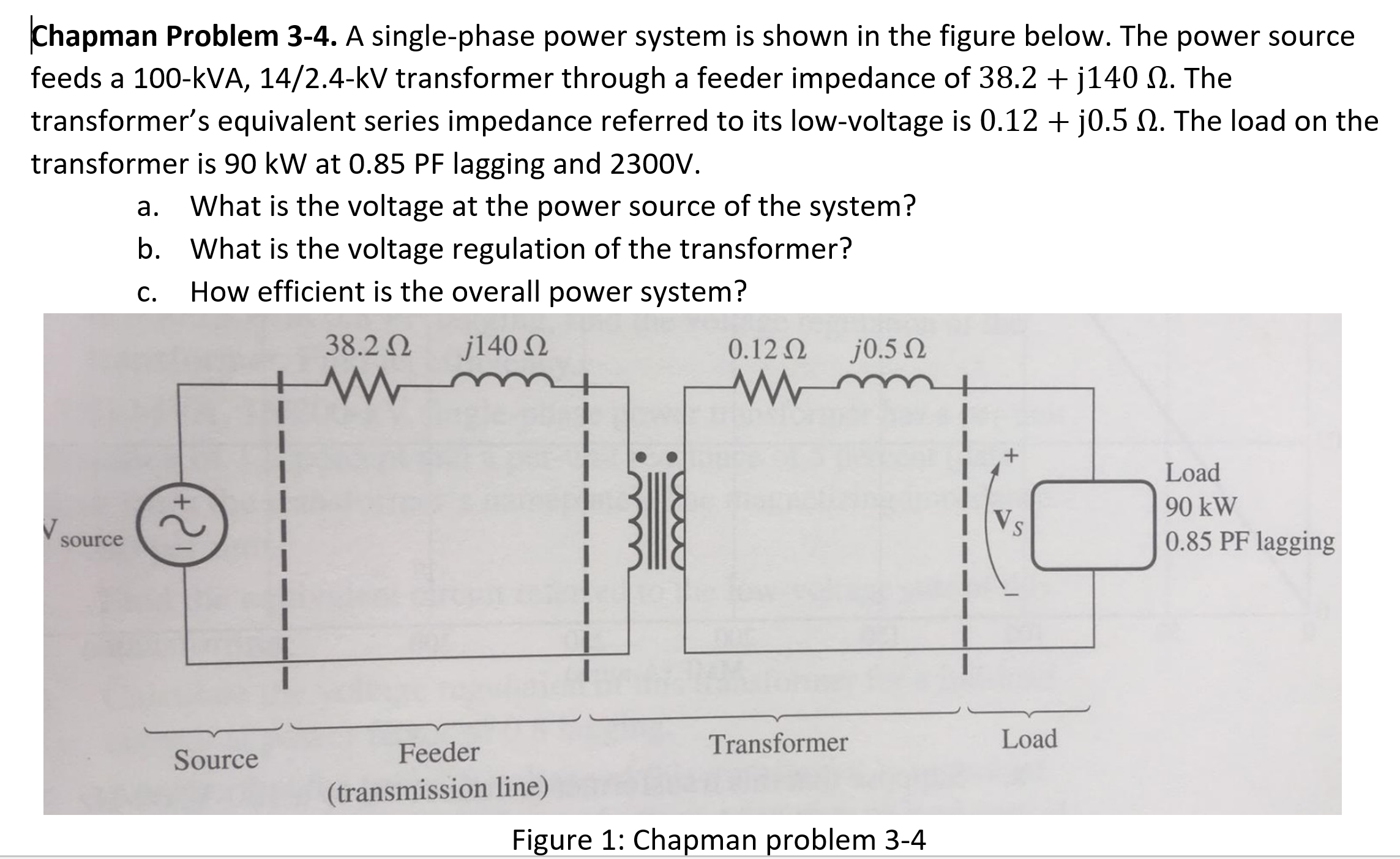

Transcribed Image Text:Chapman Problem 3-4. A single-phase power system is shown in the figure below. The power source
feeds a 100-kVA, 14/2.4-kV transformer through a feeder impedance of 38.2 + j140 N. The
transformer's equivalent series impedance referred to its low-voltage is 0.12 + j0.5 N. The load on the
transformer is 90 kW at 0.85 PF lagging and 2300V.
а.
What is the voltage at the power source of the system?
b. What is the voltage regulation of the transformer?
How efficient is the overall power system?
С.
Expert Solution
This question has been solved!
Explore an expertly crafted, step-by-step solution for a thorough understanding of key concepts.

This is a popular solution

Trending nowThis is a popular solution!

Step by stepSolved in 3 steps with 3 images

Knowledge Booster


Learn more about
Need a deep-dive on the concept behind this application? Look no further. Learn more about this topic, electrical-engineering and related others by exploring similar questions and additional content below.Similar questions
- A single-phase step-down transformer is rated 13MVA,66kV/11.5kV. With the 11.5 kV winding short-circuited, rated current flows when the voltage applied to the primary is 5.5 kV. The power input is read as 100 kW. Determine Req1andXeq1 in ohms referred to the high-voltage winding.arrow_forwardConsider the three single-phase two-winding transformers shown in Figure 3.37. The high-voltage windings are connected in Y. (a) For the low-voltage side, connect the windings in , place the polarity marks, and label the terminals a, b, and c in accordance with the American standard. (b) Relabel the terminals a, b, and c such that VAN is 90 out of phase with Va for positive sequence.arrow_forwardThe ratings of a three-phase three-winding transformer are Primary(1): Y connected 66kV,15MVA Secondary (2): Y connected, 13.2kV,10MVA Tertiary (3): A connected, 2.3kV,5MVA Neglecting winding resistances and exciting current, the per-unit leakage reactances are X12=0.08 on a 15-MVA,66-kV base X13=0.10 on a 15-MVA,66-kV base X23=0.09 on a 10-MVA,13.2-kV base (a) Determine the per-unit reactances X1,X2,X3 of the equivalent circuit on a 15-MVA,66-kV base at the primary terminals. (b) Purely resistive loads of 7.5 MW at 13.2 kV and 5 MW at 2.3kV are connected to the secondary and tertiary sides of the transformer, respectively. Draw the per- unit impedance diagram, showing the per-unit impedances on a 15-MVA,66-kV base at the primary terminals.arrow_forward
- An ideal transformer has no real or reactive power loss. (a) True (b) Falsearrow_forward(a) An ideal single-phase two-winding transformer with turns ratio at=N1/N2 is connected with a series impedance Z2 across winding 2. If one wants to replace Z2, with a series impedance Z1 across winding 1 and keep the terminal behavior of the two circuits to be identical, find Z1 in terms of Z2. (b) Would the above result be true if instead of a series impedance there is a shunt impedance? (c) Can one refer a ladder network on the secondary (2) side to the primary (1) side simply by multiplying every impedance byat2 ?arrow_forwardFor an ideal 2-winding transformer, an impedance Z2 connected across winding 2 (secondary) is referred to winding 1 (primary) by multiplying Z2 by (a) The turns ratio (N1/N2) (b) The square of the turns ratio (N1/N2)2 (c) The cubed turns ratio (N1/N2)3arrow_forward
- 1-A single-phase power system is shown in Figure below. The power source feeds a 100- kVA 14/2.4-kV transformer through a feeder impedance of 40.0 + j150 &. The transformer's equivalent series impedance referred to its low-voltage side is 0.12 + j0.5 &. The load on the transformer is 90 kW at 0.80 PF lagging and 2300 V. 40n j150n 0.12n j0.5n Load 90 kW 0.85 PF lagging source Source Feeder Transformer Load (transmission line) (a) What is the voltage at the power source of the system? (b) What is the power losses in the feeder?arrow_forwardThe rated voltages of a single-phase transformer are 2000 V and 200 V in its primary and secondary respectively. The shunt impedance can be modelled with a resistance of 14000 ohms in parallel with a reactance of 1100 ohm, both refer to primary side. The primary and secondary series impedances are (0.12+j 0.35) ohms and (0.0012+j 0.0035) ohms respectively. A load is connected to the secondary side of transformer, draws 810 KVA with a lagging power factor of 0.85. The load voltage is same as rated voltage, that is 200 V. ▪ Use per unit method for analysis and find the voltage on primary side in pu.arrow_forwardI need the answer quicklyarrow_forward
- Two 100-kW, single-phase transformers are connected in parallel both on the primary and secondary. One transformer has an ohmic drop of 0.5% at full-load and an inductive drop of 8% at full-load current. The other has an ohmic drop of 0.75% and an inductive drop of 2%. Show how they will share a load of 180 kW at 0.9 p.f.arrow_forward3. A non-ideal 1-phase transformer has turns ratio 5:1 with 120Vac primary. The primary impedance is 1 + j1 Ohms, and the secondary impedance is 0.2 + j0.2 Ohms. Assume the core impedance (R0 and X0) can be neglected. A resistive load of 12 Ohms is connected to the secondary. What is the primary current magnitude? What is the secondary voltage magnitude? What is the efficiency of this transformer with this load?arrow_forwardA three-phase transformer bank is connected wye–delta. The primary voltage is 12,470 V, and the secondary voltage is 480 V. The total capacity of the transformer bank is 450 kVA. One of the three transformers that form the three-phase bank develops a shorted primary winding and becomes unusable. A suggestion is made to reconnect the bank for operation as an open-delta. Can the two remaining transformers be connected open-delta? Explain your answer as to why they can or why they cannot be connected as an open-delta. If they can be reconnected open-delta, what would be the output capacity of the two remaining transformers?arrow_forward
arrow_back_ios
SEE MORE QUESTIONS
arrow_forward_ios
Recommended textbooks for you
- Power System Analysis and Design (MindTap Course ...Electrical EngineeringISBN:9781305632134Author:J. Duncan Glover, Thomas Overbye, Mulukutla S. SarmaPublisher:Cengage Learning
 Electricity for Refrigeration, Heating, and Air C...Mechanical EngineeringISBN:9781337399128Author:Russell E. SmithPublisher:Cengage Learning
Power System Analysis and Design (MindTap Course ...
Electrical Engineering
ISBN:9781305632134
Author:J. Duncan Glover, Thomas Overbye, Mulukutla S. Sarma
Publisher:Cengage Learning
Electricity for Refrigeration, Heating, and Air C...
Mechanical Engineering
ISBN:9781337399128
Author:Russell E. Smith
Publisher:Cengage Learning