Elements Of Electromagnetics
7th Edition
ISBN: 9780190698614
Author: Sadiku, Matthew N. O.
Publisher: Oxford University Press
expand_more
expand_more
format_list_bulleted
Question

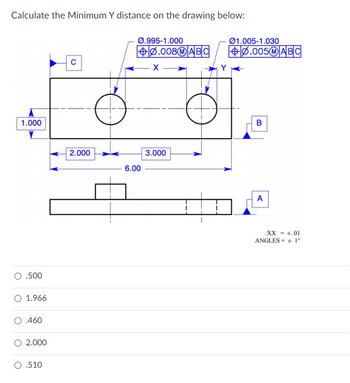
Transcribed Image Text:**Calculate the Minimum Y Distance on the Drawing Below:**
The image depicts a technical drawing with a rectangular object featuring two circular holes. Key dimensions and geometric tolerances are labeled as follows:
1. **Dimensions:**
- The height of the rectangle is labeled as 1.000.
- The width is divided into sections: 2.000 (left section), 3.000 (middle section), and the total width is 6.00.
2. **Hole Dimensions and Tolerances:**
- The left hole has a diameter range of Ø0.995 to Ø1.000 with a geometric tolerance indicated by a feature control frame (⌀0.008, M, A, B, C).
- The right hole has a diameter range of Ø1.005 to Ø1.030 with another feature control frame (⌀0.005, M, A, B, C).
3. **Views:**
- Top view showing the placement of the holes.
- A side view illustrating the depth and showing datum triangles A, B, and C.
4. **Datum and Angles:**
- Datum references: A, B, and C are indicated for geometric control.
- Tolerances are specified as .XX = ± 0.01, with angles ± 1°.
**Options for the Minimum Y Distance are:**
- 0.500
- 1.966
- 0.460
- 2.000
- 0.510
Expert Solution
arrow_forward
Step 1
given;
Step by stepSolved in 3 steps

Knowledge Booster
Learn more about
Need a deep-dive on the concept behind this application? Look no further. Learn more about this topic, mechanical-engineering and related others by exploring similar questions and additional content below.Similar questions
- Compute a little more by taking the integralinii) terms up to the 5th order ii) taking the terms up to the 7th orderarrow_forwardusing AutoCADarrow_forwardCalculate the Maximum X distance on the drawing below: 1.000 .510 O 3.000 2.009 O 1.996 2.000 с 2.000 Ø.995-1.000 6.00 0.008 MABC X 3.000 Y 01.005-1.030 +0.005MABC B A XX = .01 ANGLES= ± 1°arrow_forward
arrow_back_ios
SEE MORE QUESTIONS
arrow_forward_ios
Recommended textbooks for you
 Elements Of ElectromagneticsMechanical EngineeringISBN:9780190698614Author:Sadiku, Matthew N. O.Publisher:Oxford University Press
 Mechanics of Materials (10th Edition)Mechanical EngineeringISBN:9780134319650Author:Russell C. HibbelerPublisher:PEARSON
 Thermodynamics: An Engineering ApproachMechanical EngineeringISBN:9781259822674Author:Yunus A. Cengel Dr., Michael A. BolesPublisher:McGraw-Hill Education
 Control Systems EngineeringMechanical EngineeringISBN:9781118170519Author:Norman S. NisePublisher:WILEY
 Mechanics of Materials (MindTap Course List)Mechanical EngineeringISBN:9781337093347Author:Barry J. Goodno, James M. GerePublisher:Cengage Learning
 Engineering Mechanics: StaticsMechanical EngineeringISBN:9781118807330Author:James L. Meriam, L. G. Kraige, J. N. BoltonPublisher:WILEY

Elements Of Electromagnetics
Mechanical Engineering
ISBN:9780190698614
Author:Sadiku, Matthew N. O.
Publisher:Oxford University Press

Mechanics of Materials (10th Edition)
Mechanical Engineering
ISBN:9780134319650
Author:Russell C. Hibbeler
Publisher:PEARSON

Thermodynamics: An Engineering Approach
Mechanical Engineering
ISBN:9781259822674
Author:Yunus A. Cengel Dr., Michael A. Boles
Publisher:McGraw-Hill Education

Control Systems Engineering
Mechanical Engineering
ISBN:9781118170519
Author:Norman S. Nise
Publisher:WILEY

Mechanics of Materials (MindTap Course List)
Mechanical Engineering
ISBN:9781337093347
Author:Barry J. Goodno, James M. Gere
Publisher:Cengage Learning

Engineering Mechanics: Statics
Mechanical Engineering
ISBN:9781118807330
Author:James L. Meriam, L. G. Kraige, J. N. Bolton
Publisher:WILEY