
Electricity for Refrigeration, Heating, and Air Conditioning (MindTap Course List)
10th Edition
ISBN: 9781337399128
Author: Russell E. Smith
Publisher: Cengage Learning
expand_more
expand_more
format_list_bulleted
Related questions
Question
Can you calculate the needed values. When it ask me to measure the values do I attach the function generator and use the values mentioned below? or do i leave the function generator off and measure? Any tips on how to connect the multimeters would be appreciated but not primary request.

Transcribed Image Text:C1
Input
R1
22
ww
R3
output
Q1
R4
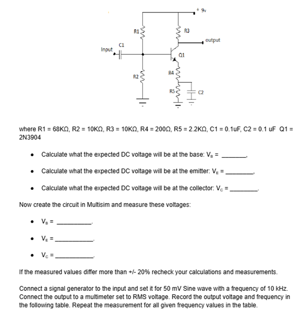
where R1 = 68KQ, R2 = 10KQ, R3 = 10KQ, R4 = 2000, R5 = 2.2KQ, C1 = 0.1uF, C2 = 0.1 uF Q1 =
2N3904
⚫ Calculate what the expected DC voltage will be at the base: V₂ =
⚫ Calculate what the expected DC voltage will be at the emitter: V₁ =
⚫ Calculate what the expected DC voltage will be at the collector: Vc =
Now create the circuit in Multisim and measure these voltages:
VE =
V₁ =.
If the measured values differ more than +/- 20% recheck your calculations and measurements.
Connect a signal generator to the input and set it for 50 mV Sine wave with a frequency of 10 kHz.
Connect the output to a multimeter set to RMS voltage. Record the output voltage and frequency in
the following table. Repeat the measurement for all given frequency values in the table.
Expert Solution
This question has been solved!
Explore an expertly crafted, step-by-step solution for a thorough understanding of key concepts.

Step by stepSolved in 2 steps

Knowledge Booster

Similar questions
- An RC series circuit is connected to a 120-V, 60-Hz power source. The resistor is 25 and has a voltage drop of 65 volts. What is the capacitance of the capacitor?arrow_forwardQuestion V.Full explain this question and text typing work only We should answer our question within 2 hours takes more time then we will reduce Rating Dont ignore this linearrow_forwardC'uk Converter Design A C'uk converter has an input of 12 V and is to have an output of - 24 V supplying a 60 W load. Select the duty ratio, the switching frequency, the inductor sizes such that the change in inductor currents is no more than 12 percent of the average inductor current, the output ripple voltage is no more than 1.5 percent, and the ripple voltage across C1 is no more than 3 percent.arrow_forward
- Draw the small signal equivalent circuit of the following circuit. Note that C1 and C2 are large AC coupling capacitors. 5 VIO C1 RF Q1 C2 fem RL Voarrow_forwardGiven the following with Q = 0 as initial state, What do the Q and Q0 waveforms look like? SET RESET Qarrow_forwardd) Design (Find the values of the R₁, R2, and C₁) an astable multivibrator circuit to have an output waveform as shown below in the figure (tH = 375µs and t₁ = 125µs). (Assume C₁ = C₂ and R₁ # R₂) and determine the frequency of oscillation and the duty cycle. R1: R2 C1 Q Vcc 4 555 5 C2 10nF I 8 1 3L -OVO tH = 375.0us tL = 125.0usarrow_forward
- Reset WED W=O W =l EhD DII W=0 Derive the following state-table Present state Next state output z2zlz0 W=0 W=1 A 000 B 001 C 010 D 011 E 100arrow_forwardPlease try to understand the solution and try to answer in typing format please ASAP for the Plarrow_forwardDon't know what these values are? What is H ? How can they add them?arrow_forward
- Why this happening to my circuit? I am inputting a 0-3.3 V sine wave into my voltage follower circuit using NE5532P. At the output I am seeing 0-3.3 V sine wave as expected. However, when I add a 1000 uF capacitor and a loudspeaker to listen to the sine wave my wave is clipped and its reading -800 mV for min and +680 mV for max on the oscilloscope. How do I fix this so that I only listen to 0-3.3 V sine wave? I'm in the lab and this is confusing to me.arrow_forwardDUC 1. Is the waveform on VT out terminal an ASK modulated signal? TS PROD 2. Is the waveform on VT out terminal an OOK modulated signal? ASK Modulator/Demodulator U1 VD Signal in VT out X1 W R1 VC Carrier in w x2 100K 3 Y1 4 Y2 AD633 Z VR1 10K VR1 Multiplier(1) I U2 Vx out X1 W R3 2 w x2 In2 100K 3 ۲۱ I Y2 AD633 Z VR2 R2 10K C4 100K VR2 Multiplier(2) +5V 200p R5 R6 R101K ww w 2.7K 22K 1N4148 D1 559 VE out D+ In(ac) 6 0H 200p HH 6 VLP out Vo out U3 VR 0.01 0.1u R8 VR3 ww 50K Envelope Detector 10K U3 LF356 VR3 LPF U4Σ LM311 Comparator U5 PLL in CS HH 14 SIGN IN PC1OUT 2 0.1u 6 CIA PULSES PHASE(2) COMPARATOR OUT 13 C10 HT 150p R16 ww R12 VSO 18K C6 200p VCO OUT 4 IK in R14 C9 10 O w H VLO out 6 7 Cle 15K VCO 150p 06 11 R1 CD4046 VCO IN 9 VR5 1K 12 R2 0.0047u C7 I Demod C8 out 10 SOURCE FOLLOWER R11 100K INH COMP IN 5 3 VR4 +5V+12V GND-12V о HTO 0.1u R13 10K I PL Figure 18-10 KL-94005 module VR5 R15 U6Σ OP37 BPFarrow_forwardNegative Clamping Circuit: Can you explain why the output voltage gets shifted down logically?arrow_forward
arrow_back_ios
SEE MORE QUESTIONS
arrow_forward_ios
Recommended textbooks for you
- Electricity for Refrigeration, Heating, and Air C...Mechanical EngineeringISBN:9781337399128Author:Russell E. SmithPublisher:Cengage Learning
 Delmar's Standard Textbook Of ElectricityElectrical EngineeringISBN:9781337900348Author:Stephen L. HermanPublisher:Cengage Learning
Electricity for Refrigeration, Heating, and Air C...
Mechanical Engineering
ISBN:9781337399128
Author:Russell E. Smith
Publisher:Cengage Learning
Delmar's Standard Textbook Of Electricity
Electrical Engineering
ISBN:9781337900348
Author:Stephen L. Herman
Publisher:Cengage Learning