
Power System Analysis and Design (MindTap Course List)
6th Edition
ISBN: 9781305632134
Author: J. Duncan Glover, Thomas Overbye, Mulukutla S. Sarma
Publisher: Cengage Learning
expand_more
expand_more
format_list_bulleted
Related questions
Question
thumb_up100%
Please answer all parts of the solution with step by step working out thank you
(please handwrite the solutions)
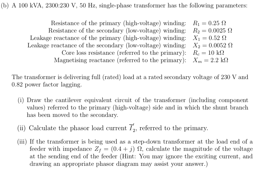

Transcribed Image Text:(b) A 100 kVA, 2300:230 V, 50 Hz, single-phase transformer has the following parameters:
Resistance of the primary (high-voltage) winding:
Resistance of the secondary (low-voltage) winding:
Leakage reactance of the primary (high-voltage) winding:
Leakage reactance of the secondary (low-voltage) winding:
Core loss resistance (referred to the primary):
Magnetising reactance (referred to the primary):
R₁ = 0.25 Ω
R₂ = 0.0025 2
X₁ = 0.52
X2 = 0.0052 Ω
Rc = 10 k
= 2.2 ΚΩ
Xm
The transformer is delivering full (rated) load at a rated secondary voltage of 230 V and
0.82 power factor lagging.
(i) Draw the cantilever equivalent circuit of the transformer (including component
values) referred to the primary (high-voltage) side and in which the shunt branch
has been moved to the secondary.
(ii) Calculate the phasor load current Ĭ2, referred to the primary.
(iii) If the transformer is being used as a step-down transformer at the load end of a
feeder with impedance Zƒ = (0.4 + j) ₁, calculate the magnitude of the voltage
at the sending end of the feeder (Hint: You may ignore the exciting current, and
drawing an appropriate phasor diagram may assist your answer.)
Expert Solution
This question has been solved!
Explore an expertly crafted, step-by-step solution for a thorough understanding of key concepts.

Step by stepSolved in 2 steps with 5 images

Knowledge Booster

Similar questions
- For a short-circuit test on a 2-winding transformer, with one winding shorted, can you apply the rated voltage on the other winding? (a) Yes (b) Noarrow_forwardThree single-phase, two-winding transformers, each rated 450MVA,20kV/288.7kV, with leakage reactance Xeq=0.10perunit, are connected to form a three-phase bank. The high-voltage windings are connected in Y with a solidly grounded neutral. Draw the per-unit equivalent circuit if the low-voltage windings are connected (a) in with American standard phase shift or (b) in Y with an open neutral. Use the transformer ratings as base quantities. Winding resistances and exciting current are neglected.arrow_forwardIn developing per-unit circuits of systems such as the one shown in Figure 3.10. when moving across a transformer, the voltage base is changed in proportion to the transformer voltage ratings. (a) True (b) Falsearrow_forward
- For developing per-unit equivalent circuits of single-phase three-winding transformer, a common Sbase is selected for all three windings and voltage bases are selected in proportion to the rated voltage of the windings (a) True (b) Falsearrow_forwardThe ideal transformer windings are eliminated from the per-unit equivalent circuit of a transformer. (a) True (b) Falsearrow_forwardA single-phase, 50-kVA,2400/240-V,60-Hz distribution transformer has the following parameters: Resistance of the 2400-V winding: R1=0.75 Resistance of the 240-V winding: R2=0.0075 Leakage reactance of the 2400-V winding: X1=1.0 Leakage reactance of the 240-V winding: X2=0.01 Exciting admittance on the 240-V side =0.003j0.02S (a) Draw the equivalent circuit referred to the high-voltage side of the transformer. (b) Draw the equivalent circuit referred to the low-voltage side of the transformer. Show the numerical values of impedances on the equivalent circuits.arrow_forward
- Why is it important to reduce the moisture within a transformer to acceptable levels during transformer installation?arrow_forwardAn ideal transformer has no real or reactive power loss. (a) True (b) Falsearrow_forwardThe direct electrical connection of the windings allows transient over voltages to pass through the auto transfonner more easily, and that is an important disadvantage of the autotransformer. (a) True (b) Falsearrow_forward
- Consider a bank of this single-phase two-winding transformers whose high-voltage terminals are connected to a three-phase, 13.8-kV feeder. The low-voltage terminals are connected to a three-phase substation load rated 2.0 MVA and 2.5 kV. Determine the required voltage, current, and MVA ratings of both windings of each transformer, when the high-voltage/low- voltage windings are connected (a) Y-, (b) -Y, (c) Y-Y, and (d) -.arrow_forwardWith the American Standard notation, in either a Y-or-Y transformer, positive- sequen quantities on the high-voltage side shall lead their corresponding quantities on the low-voltage side by 30. (a) True (b) Falsearrow_forwardThree single-phase two-winding transformers, each rated 25MVA,54.2/5.42kV, are connected to form a three-phase Y- bank with a balanced Y-connected resistive load of 0.6 per phase on the low-voltage side. By choosing a base of 75 MVA (three phase) and 94 kV (line-to-line) for the high-voltage side of the transformer bank, specify the base quantities for the low-voltage side. Determine the per-unit resistance of the load on the base for the low-voltage side. Then determine the load resistance RL in ohms referred to the high-voltage side and the per-unit value of this load resistance on the chosen base.arrow_forward
arrow_back_ios
SEE MORE QUESTIONS
arrow_forward_ios
Recommended textbooks for you
- Power System Analysis and Design (MindTap Course ...Electrical EngineeringISBN:9781305632134Author:J. Duncan Glover, Thomas Overbye, Mulukutla S. SarmaPublisher:Cengage Learning
Power System Analysis and Design (MindTap Course ...
Electrical Engineering
ISBN:9781305632134
Author:J. Duncan Glover, Thomas Overbye, Mulukutla S. Sarma
Publisher:Cengage Learning