
Introductory Circuit Analysis (13th Edition)
13th Edition
ISBN: 9780133923605
Author: Robert L. Boylestad
Publisher: PEARSON
expand_more
expand_more
format_list_bulleted
Related questions
Concept explainers
Question
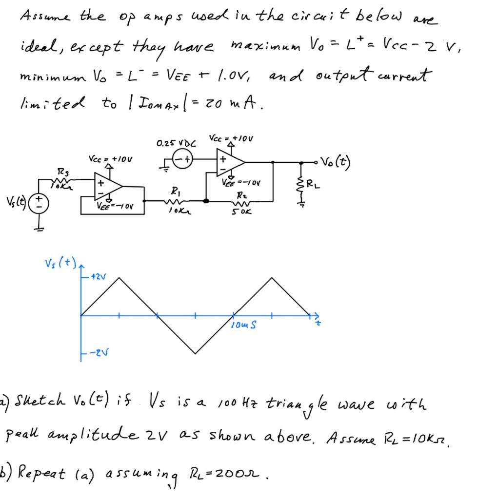

Transcribed Image Text:Assume the op amps used in the circuit below are
maximum Vo
ideal, except they have
minimum Vo = L = VEE + 1.0V, and output current
limited to | IOMAX | = 20 mA.
Vs (t)(
vh(+
RS
Toka
Vs (+)
Vcc= +10V
↑
+
VEE-1 OV
42V
-2V
0.25 VDC
R₁
ww
10K₂
Vcc = +10V
수
+
VEE=-1 OV
R₂
ww
50K
10m S
+
Lt = Vcc - 2 V,
=
{RL
• Vo(t)
2) Sketch Vo(t) if Vs is a 100 Hz triangle wave with
peall amplitude 2V as shown above. Assume R₂ = 10ks.
b) Repeat (a) assuming RL=2002.
Expert Solution
This question has been solved!
Explore an expertly crafted, step-by-step solution for a thorough understanding of key concepts.

This is a popular solution

Trending nowThis is a popular solution!

Step by stepSolved in 6 steps with 5 images

Knowledge Booster


Learn more about
Need a deep-dive on the concept behind this application? Look no further. Learn more about this topic, electrical-engineering and related others by exploring similar questions and additional content below.Similar questions
- Some of the exercises show op-amps with a positive supply voltage but no information about negative supply voltages. Whenever this is encountered, assume the negative supply voltage has the same magnitude as that of the positive supplyarrow_forward2 Figure 3 shows an operational amplifier circuit with two current sources to model its bias currents. The op-amp can be considered as ideal. ) !-10µA Vi* Rx Vo R2 I=10µA R1 Figure 3 (D) Determine the output voltage of the amplifier for Vi=0.1V, Rx=00.arrow_forwardAn op-amp is connected to power supplies so that its Vcc value is 15V. It has an open-loop gain of 8 x 10⁶ V/V, and the non-inverting input is 1 µV. If the output voltage is equal to 2V, what is the magnitude of the voltage connected to the inverting terminal?arrow_forward
arrow_back_ios
arrow_forward_ios
Recommended textbooks for you
- Introductory Circuit Analysis (13th Edition)Electrical EngineeringISBN:9780133923605Author:Robert L. BoylestadPublisher:PEARSON
 Delmar's Standard Textbook Of ElectricityElectrical EngineeringISBN:9781337900348Author:Stephen L. HermanPublisher:Cengage Learning
 Programmable Logic ControllersElectrical EngineeringISBN:9780073373843Author:Frank D. PetruzellaPublisher:McGraw-Hill Education
  Fundamentals of Electric CircuitsElectrical EngineeringISBN:9780078028229Author:Charles K Alexander, Matthew SadikuPublisher:McGraw-Hill Education
 Electric Circuits. (11th Edition)Electrical EngineeringISBN:9780134746968Author:James W. Nilsson, Susan RiedelPublisher:PEARSON
 Engineering ElectromagneticsElectrical EngineeringISBN:9780078028151Author:Hayt, William H. (william Hart), Jr, BUCK, John A.Publisher:Mcgraw-hill Education,
Introductory Circuit Analysis (13th Edition)
Electrical Engineering
ISBN:9780133923605
Author:Robert L. Boylestad
Publisher:PEARSON
Delmar's Standard Textbook Of Electricity
Electrical Engineering
ISBN:9781337900348
Author:Stephen L. Herman
Publisher:Cengage Learning
Programmable Logic Controllers
Electrical Engineering
ISBN:9780073373843
Author:Frank D. Petruzella
Publisher:McGraw-Hill Education
Fundamentals of Electric Circuits
Electrical Engineering
ISBN:9780078028229
Author:Charles K Alexander, Matthew Sadiku
Publisher:McGraw-Hill Education
Electric Circuits. (11th Edition)
Electrical Engineering
ISBN:9780134746968
Author:James W. Nilsson, Susan Riedel
Publisher:PEARSON
Engineering Electromagnetics
Electrical Engineering
ISBN:9780078028151
Author:Hayt, William H. (william Hart), Jr, BUCK, John A.
Publisher:Mcgraw-hill Education,