Introductory Circuit Analysis (13th Edition)
13th Edition
ISBN: 9780133923605
Author: Robert L. Boylestad
Publisher: PEARSON
expand_more
expand_more
format_list_bulleted
Question

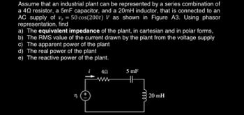
Transcribed Image Text:Assume that an industrial plant can be represented by a series combination of
a 40 resistor, a 5mF capacitor, and a 20mH inductor, that is connected to an
AC supply of vs = 50 cos(200t) V as shown in Figure A3. Using phasor
representation, find
a) The equivalent impedance of the plant, in cartesian and in polar forms,
b) The RMS value of the current drawn by the plant from the voltage supply
c) The apparent power of the plant
d) The real power of the plant
e) The reactive power of the plant.
4Ω
5 mF
m
20 mH
Expert Solution
This question has been solved!
Explore an expertly crafted, step-by-step solution for a thorough understanding of key concepts.
Step by stepSolved in 4 steps

Knowledge Booster
Learn more about
Need a deep-dive on the concept behind this application? Look no further. Learn more about this topic, electrical-engineering and related others by exploring similar questions and additional content below.Similar questions
- Write a report to compare between Ac Through capacitance and AC through in inductance then: For the circuit shown beside, find The average power delivered to the * .circuit jón a 1000 v 82 -j72 barrow_forwardP5.46. Find the phasors for the voltage and the cur- rents of the circuit shown in Figure P5.46. Construct a phasor diagram showing Is, V. IR, and IL. What is the phase relationship between V and Is? 1 H 200 2 0.5 sin(100r) (1)a Figure P5.46arrow_forwardQUESTION 4 A resistor, a capacitor, and an inductor are connected in series with a function generator. The resistor has a resistance of 1.5k2, the inductor has a reactance of 1.2kQ, and the capacitor has a reactance of 2002. The circuit has a total current of 172mA RMS. Find the total voltage. O 310V233.7 O 74.5VL-14° 188V273.2 O 44.4VL-25.3°arrow_forward
- Introduction to Ac circuits. show detailed illustration and step by step solutionarrow_forwardP5.43. Compute the complex impedance of the net- work shown in Figure P5.43 for w = 500. Repeat for w = 1000 and w = 2000. Give the answers in both polar and rectangular forms. 10 μ 100 mH 100 2 Figure P5.43arrow_forwardProblem #7) Specify whether each of the statements are TRUE or FALSE. D Reactive Power is a measure of the average power consumed by reactive (capacitive and inductive) loads. When connected to an AC voltage source, the instantaneous power (rate of energy transfer) supplied to a resistor varies at a frequency that is 2x the frequency of the applied source voltage. The magnitude of the impedance of a capacitor supplied by an AC source will increase as the source frequency increases. An AC source that has an RMS magnitude of 100V will supply the same average power to a resistor compared to a 100V DC source. The voltage across a capacitor is proportional to the rate of change of the current flowing through the capacitor. The magnitude of the impedance of a resistor supplied by an AC source does not vary as the source frequency increases. A complex impedance Z=R+jX, that has non-zero resistive and reactive components, will consume both real and reactive power when supplied by an AC source.…arrow_forward
- Add the two voltages below together (phasor voltages are RMS). ?ଵ =60 ? ∠ 0° ?ଶ =80 ?∠ 270° a) What is the resultant as a phasor using RMS voltage and degrees? b) What is the resultant voltage as a sinusoidal equation if the frequency is 100 Hz?arrow_forwardConsider the situation shown in (Figure 1). A 1000-V-rms source delivers power to a load. The load consumes 140 kW with a power factor of 55 percent lagging.  Time remaining: 00:07:30 Electrical Engineering Consider the situation shown in (Figure 1). A 1000-V-rms source delivers power to a load. The load consumes 140 kW with a power factor of 55 percent lagging. 1- Find the phasor II, assuming that the capacitor is not connected to the circuit. Enter your answer using polar notation. Express argument in degrees. 2-Find the value of the capacitance that must be connected in parallel with the load to achieve a power factor of 100 percent. Express your answer to three significant figures and include the appropriate units. 3-Usually, power-systems engineers rate capacitances used for power-factor correction in terms of their reactive power rating. What is the rating of this capacitance in kVAR? Express your answer using three significant figures. 4-Assuming that this…arrow_forwardThe circuit in figure 2 is operating in the sinusoidal steady state, I1=0.520 A and V1-50290° V. Use superposition to find phasor response I, L1 R2 j25 500 Ix R1 250 11 C1 V1 -j50 Figure 2arrow_forward
arrow_back_ios
arrow_forward_ios
Recommended textbooks for you
 Introductory Circuit Analysis (13th Edition)Electrical EngineeringISBN:9780133923605Author:Robert L. BoylestadPublisher:PEARSON
 Delmar's Standard Textbook Of ElectricityElectrical EngineeringISBN:9781337900348Author:Stephen L. HermanPublisher:Cengage Learning
 Programmable Logic ControllersElectrical EngineeringISBN:9780073373843Author:Frank D. PetruzellaPublisher:McGraw-Hill Education
 Fundamentals of Electric CircuitsElectrical EngineeringISBN:9780078028229Author:Charles K Alexander, Matthew SadikuPublisher:McGraw-Hill Education
 Electric Circuits. (11th Edition)Electrical EngineeringISBN:9780134746968Author:James W. Nilsson, Susan RiedelPublisher:PEARSON
 Engineering ElectromagneticsElectrical EngineeringISBN:9780078028151Author:Hayt, William H. (william Hart), Jr, BUCK, John A.Publisher:Mcgraw-hill Education,

Introductory Circuit Analysis (13th Edition)
Electrical Engineering
ISBN:9780133923605
Author:Robert L. Boylestad
Publisher:PEARSON

Delmar's Standard Textbook Of Electricity
Electrical Engineering
ISBN:9781337900348
Author:Stephen L. Herman
Publisher:Cengage Learning

Programmable Logic Controllers
Electrical Engineering
ISBN:9780073373843
Author:Frank D. Petruzella
Publisher:McGraw-Hill Education

Fundamentals of Electric Circuits
Electrical Engineering
ISBN:9780078028229
Author:Charles K Alexander, Matthew Sadiku
Publisher:McGraw-Hill Education

Electric Circuits. (11th Edition)
Electrical Engineering
ISBN:9780134746968
Author:James W. Nilsson, Susan Riedel
Publisher:PEARSON

Engineering Electromagnetics
Electrical Engineering
ISBN:9780078028151
Author:Hayt, William H. (william Hart), Jr, BUCK, John A.
Publisher:Mcgraw-hill Education,