Introductory Circuit Analysis (13th Edition)
13th Edition
ISBN: 9780133923605
Author: Robert L. Boylestad
Publisher: PEARSON
expand_more
expand_more
format_list_bulleted
Question
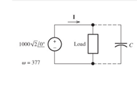
Consider the situation shown in (Figure 1). A 1000-V-rms source delivers power to a load. The load consumes 140 kW with a power factor of 55 percent lagging.

Time remaining:
00:07:30
Electrical Engineering
Consider the situation shown in (Figure 1). A 1000-V-rms source delivers power to a load. The load consumes 140 kW with a power factor of 55 percent lagging.
1- Find the phasor II, assuming that the capacitor is not connected to the circuit.
Enter your answer using polar notation. Express argument in degrees.
2-Find the value of the capacitance that must be connected in parallel with the load to achieve a power factor of 100 percent.
Express your answer to three significant figures and include the appropriate units.
3-Usually, power-systems engineers rate capacitances used for power-factor correction in terms of their reactive power rating. What is the rating of this capacitance in kVAR?
Express your answer using three significant figures.
4-Assuming that this capacitance is connected, find the new value for the phasor I.
Enter your answer using polar notation. Express argument in degrees.

Transcribed Image Text:1000 v2/0°
Load
C
w = 377
Expert Solution
This question has been solved!
Explore an expertly crafted, step-by-step solution for a thorough understanding of key concepts.
This is a popular solution
Trending nowThis is a popular solution!
Step by stepSolved in 2 steps with 2 images

Knowledge Booster
Learn more about
Need a deep-dive on the concept behind this application? Look no further. Learn more about this topic, electrical-engineering and related others by exploring similar questions and additional content below.Similar questions
- Suppose I have two peak phasor voltages, V, = 100245° and V, = 75Z-60°. Circle Your Choices: I. The frequencies associated with the phasors are (0 Hz, 60 Hz, 50 Hz, Unknown). II. The rms value of the first phasor is (100, 70.7, 141, 200) volts. III. If you want to add these two phasors, the frequencies must be (60 Hz, 50 Hz, The same, Integer multiples of a given frequency.)arrow_forwardA current of 2.5 A through a neon light advertisement is supplied by a 115 V RMS voltage source. The current lags the voltage by 30 degrees. Find the impedance of the light, the real power dissipated by it, and its power factor.arrow_forwardProblem #1) Given the following DC circuit that is operating at steady-state: MW 24V IDC 60 Ohms 100 + Ohms 40uF Determine IDC and VR in the circuit as shown VR 120 Ohms 20mHarrow_forward
- Consider the plot shown in (Figure 1). Suppose that Vm = 6.5 V. Part A Find the rms value of the voltage waveform shown in the figure. Express your answer to three significant figures and include the appropriate units. HẢ Vrus = Value Units Submit Request Answer Provide Feedback Figure < 1 of 1 v(t) T = 2 m 4 2.arrow_forwardPower = P = 1200 W. Resistance of heating element R= 1052 Average we need to determine, a. RMS curent drawn by Kettle.arrow_forward1. Derive the formula for the RMS value for the following a) tespe RSITY SAINarrow_forward
- If the voltage and current supplied to a circuit orload by a source are˜VS = 170∠(−0.157) V ˜IS = 13∠0.28 Adeterminea. The power supplied by the source which isdissipated as heat or work in the circuit (load).b. The power stored in reactive components in thecircuit (load).c. The power factor angle and power factor.arrow_forwardQ2. For the circuit shown below, sketch the current waveforms is and io and determine the Average and RMS for both currents. a = 50° T1 50 2 ot Vs = 300 sin 100rt T2 otarrow_forwardProblem 1 Three loads A, B, and C are connected in parallel across a 1.5-kV-rms 60-Hz Source, as show below. Load A consumes 10 kW with a 90 percent lagging power factor. Load B has an apparent power of 15 kVA with an 80 percent lagging power factor. Load C consumes 12 KW with a 70 percent lagging power factor. Find the power, reactive power, and apparent power delivered by the source. What is the power factor seen by the source? State whether it is leading or lagging. Is Source A B Carrow_forward
arrow_back_ios
arrow_forward_ios
Recommended textbooks for you
 Introductory Circuit Analysis (13th Edition)Electrical EngineeringISBN:9780133923605Author:Robert L. BoylestadPublisher:PEARSON
 Delmar's Standard Textbook Of ElectricityElectrical EngineeringISBN:9781337900348Author:Stephen L. HermanPublisher:Cengage Learning
 Programmable Logic ControllersElectrical EngineeringISBN:9780073373843Author:Frank D. PetruzellaPublisher:McGraw-Hill Education
 Fundamentals of Electric CircuitsElectrical EngineeringISBN:9780078028229Author:Charles K Alexander, Matthew SadikuPublisher:McGraw-Hill Education
 Electric Circuits. (11th Edition)Electrical EngineeringISBN:9780134746968Author:James W. Nilsson, Susan RiedelPublisher:PEARSON
 Engineering ElectromagneticsElectrical EngineeringISBN:9780078028151Author:Hayt, William H. (william Hart), Jr, BUCK, John A.Publisher:Mcgraw-hill Education,

Introductory Circuit Analysis (13th Edition)
Electrical Engineering
ISBN:9780133923605
Author:Robert L. Boylestad
Publisher:PEARSON

Delmar's Standard Textbook Of Electricity
Electrical Engineering
ISBN:9781337900348
Author:Stephen L. Herman
Publisher:Cengage Learning

Programmable Logic Controllers
Electrical Engineering
ISBN:9780073373843
Author:Frank D. Petruzella
Publisher:McGraw-Hill Education

Fundamentals of Electric Circuits
Electrical Engineering
ISBN:9780078028229
Author:Charles K Alexander, Matthew Sadiku
Publisher:McGraw-Hill Education

Electric Circuits. (11th Edition)
Electrical Engineering
ISBN:9780134746968
Author:James W. Nilsson, Susan Riedel
Publisher:PEARSON

Engineering Electromagnetics
Electrical Engineering
ISBN:9780078028151
Author:Hayt, William H. (william Hart), Jr, BUCK, John A.
Publisher:Mcgraw-hill Education,