
Elements Of Electromagnetics
7th Edition
ISBN: 9780190698614
Author: Sadiku, Matthew N. O.
Publisher: Oxford University Press
expand_more
expand_more
format_list_bulleted
Related questions
Concept explainers
Question
Experiment Torque :
By means of diagram, show and explain how the two (2) conditions of equilibrium are applied on Procedure #4 setup.

Transcribed Image Text:to the same external forces that act on the object.
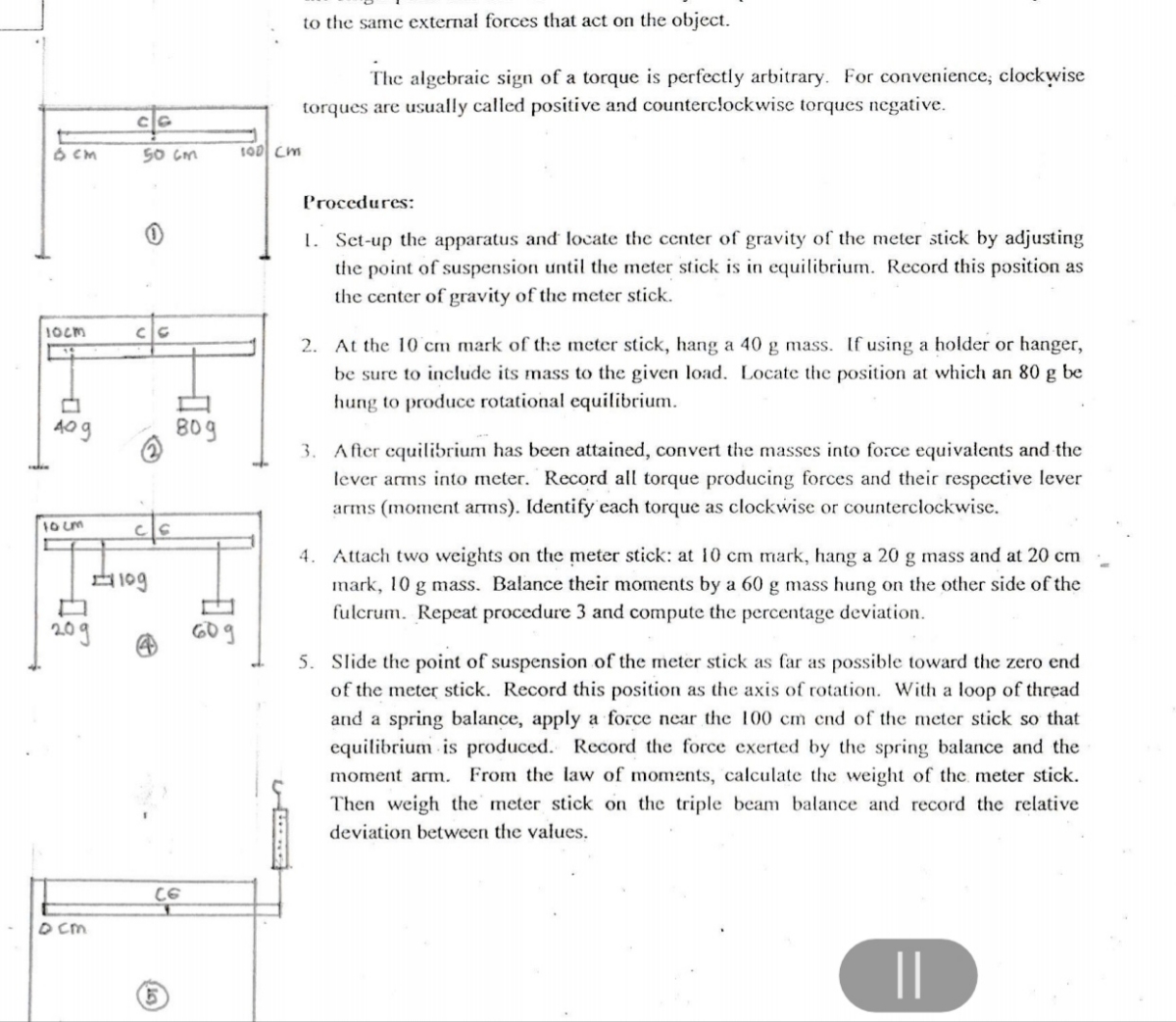
The algebraic sign of a torque is perfectly arbitrary. For convenience, clockwise
torques are usually called positive and counterclockwise torques negative.
50 Gm
100 Cm
Procedures:
1. Set-up the apparatus and locate the center of gravity of the meter stick by adjusting
the point of suspension until the meter stick is in equilibrium. Record this position as
the center of gravity of the meter stick.
1Ocm
cle
2. At the 10 cm mark of the meter stick, hang a 40 g mass. If using a holder or hanger,
be sure to include its mass to the given load. Locate the position at which an 80 g be
hung to produce rotational equilibrium.
40g
B0g
3. After equilibrium has been attained, convert the masses into force equivalents and the
lever arms into meter. Record all torque producing forces and their respective lever
arms (moment arms). Identify each torque as clockwise or counterclockwise.
10Lm
4. Attach two weights on thhe meter stick: at 10 cm mark, hang a 20 g mass and at 20 cm
mark, 10 g mass. Balance their moments by a 60 g mass hung on the other side of the
fulcrum. Repeat procedure 3 and compute the percentage deviation.
10g
5. Slide the point of suspension of the meter stick as far as possible toward the zero end
of the meter stick. Record this position as the axis of rotation. With a loop of thread
and a spring balance, apply a force near the 100 cm end of the meter stick so that
equilibrium is produced. Record the force exerted by the spring balance and the
moment arm. From the law of moments, calculate the weight of the meter stick.
Then weigh the meter stick on the triple beam balance and record the relative
deviation between the values.
CE
D Cm
||
Expert Solution
This question has been solved!
Explore an expertly crafted, step-by-step solution for a thorough understanding of key concepts.

Step by stepSolved in 4 steps with 1 images

Knowledge Booster


Learn more about
Need a deep-dive on the concept behind this application? Look no further. Learn more about this topic, mechanical-engineering and related others by exploring similar questions and additional content below.Similar questions
- Derivation of the relationship between tensile strength, contact angle and friction coefficient of a V-type beltarrow_forwardWrite down the differential equation governing the motion of the system below, where x(t) is the displacement of the system from equilibrium. LEMM in karrow_forwardFigure B b 30° 2b 30° Н. 4 of 4 Correct Note that the internal reactions at B are not included in the free-body diagram of the subsystem ABC. Part D-A tractor shovel The tractor shovel shown (Figure 4) carries a 535 kg load that has its center of mass at H. The shovel's dimensions are: a = 50.0 mm, b = 200 mm, c = 300 d = 100 mm, and e = 350 mm. Find the reaction force at E. Assume that the positive direction of the x and y axes is to the right and upward, respectively. Enter the Cartesian components of the reaction force at E separated by a comma. Express your answers in newtons to three significant figures. ► View Available Hint(s) ET, Ey = Submit VE ΑΣΦ ↓↑ vec ? Narrow_forward
- Two farmers are pushing on a gate with forces F_{A} and F_{B} applied at locations A and B respectively. The gate has a hinge at C and you may neglect the thickness of the gate. Assume that the gate is in static equilibrium. The force F_{A} is applied at an angle of alpha = 30 degrees and the force F_{B} is applied at an angle of beta = 35 degrees . The distance between B and the hinge at Cis D BC =2 m , and the distance between A and the hinge at C is D AC =3 m . Suppose that |F_{A}| = 400N Two farmers are pushing on a gate with forces F_{A} and F_{B} applied at locations A and B respectively. The gate has a hinge at C and you may neglect the thickness of the gate. Assume that the gate is in static equilibrium. The force F_{A} is applied at an angle of alpha = 30 degrees and the force F_{B} is applied at an angle of beta = 35 degrees . The distance between B and the hinge at Cis D BC =2 m , and the distance between A and the hinge at C is D AC =3 m . Suppose that |F_{A}| = 400N a)…arrow_forwarddetermine forces in cable AB, AC,ADarrow_forwardPhotoarrow_forward
- The rectangular plate shown weighs 93 lb and is held in the position shown by hinges at A and B and by cable EF. Assuming that the hinge at B does not exert any axial thrust and no couples exerted on both A and B, determine (a) the tension in the cable, (b) the reactions at A and B. Z D 12 in. 30 in. H 4 in. A E 8 in. B F 4 in. 25 in. 20 in. xarrow_forwardChapter 12, Problem 010 GO The system in the figure below is in equilibrium, with the string in the center exactly horizontal. Block A weighs 35.0 N, block B weighs 57.0 N, and angle p is 39.0°. What are Find (a) tension T1, (b) tension T2, (c) tension T3, and (d) angle 0. (a) Number Units (b) Number Units (c) Number Units (d) Number Units Click if you would like to Show Work for this question: Open Show Work GO TUTORIAL LINK TΟ ΤΕXΤ LINK TO SAMPLE PROBLEM LINK TO SAMPLE PROBLEM VIDEO MINI-LECTUREarrow_forwardProblem 5.28 The disk has a mass of 12 kg. It is suspended from a spring having an unstretched length of 400 mm. (Figure 1) Figure -8- k = 600 N/m 200 mm 1 of 1 Part A Determine the angle for equilibrium. Express your answer in degrees to three significant figures. 0 = Submit OF V—| ΑΣΦ Provide Feedback Request Answer vec ?arrow_forward
arrow_back_ios
arrow_forward_ios
Recommended textbooks for you
- Elements Of ElectromagneticsMechanical EngineeringISBN:9780190698614Author:Sadiku, Matthew N. O.Publisher:Oxford University Press
 Mechanics of Materials (10th Edition)Mechanical EngineeringISBN:9780134319650Author:Russell C. HibbelerPublisher:PEARSON
 Thermodynamics: An Engineering ApproachMechanical EngineeringISBN:9781259822674Author:Yunus A. Cengel Dr., Michael A. BolesPublisher:McGraw-Hill Education
  Control Systems EngineeringMechanical EngineeringISBN:9781118170519Author:Norman S. NisePublisher:WILEY
 Mechanics of Materials (MindTap Course List)Mechanical EngineeringISBN:9781337093347Author:Barry J. Goodno, James M. GerePublisher:Cengage Learning
 Engineering Mechanics: StaticsMechanical EngineeringISBN:9781118807330Author:James L. Meriam, L. G. Kraige, J. N. BoltonPublisher:WILEY
Elements Of Electromagnetics
Mechanical Engineering
ISBN:9780190698614
Author:Sadiku, Matthew N. O.
Publisher:Oxford University Press
Mechanics of Materials (10th Edition)
Mechanical Engineering
ISBN:9780134319650
Author:Russell C. Hibbeler
Publisher:PEARSON
Thermodynamics: An Engineering Approach
Mechanical Engineering
ISBN:9781259822674
Author:Yunus A. Cengel Dr., Michael A. Boles
Publisher:McGraw-Hill Education
Control Systems Engineering
Mechanical Engineering
ISBN:9781118170519
Author:Norman S. Nise
Publisher:WILEY
Mechanics of Materials (MindTap Course List)
Mechanical Engineering
ISBN:9781337093347
Author:Barry J. Goodno, James M. Gere
Publisher:Cengage Learning
Engineering Mechanics: Statics
Mechanical Engineering
ISBN:9781118807330
Author:James L. Meriam, L. G. Kraige, J. N. Bolton
Publisher:WILEY