Introductory Circuit Analysis (13th Edition)
13th Edition
ISBN: 9780133923605
Author: Robert L. Boylestad
Publisher: PEARSON
expand_more
expand_more
format_list_bulleted
Concept explainers
Question

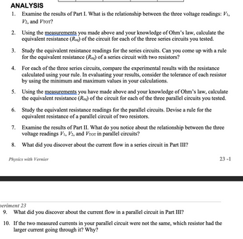
Transcribed Image Text:ANALYSIS
1. Examine the results of Part I. What is the relationship between the three voltage readings: V₁,
V2, and VTOT?
2. Using the measurements you made above and your knowledge of Ohm's law, calculate the
equivalent resistance (Req) of the circuit for each of the three series circuits you tested.
3. Study the equivalent resistance readings for the series circuits. Can you come up with a rule
for the equivalent resistance (Req) of a series circuit with two resistors?
4. For each of the three series circuits, compare the experimental results with the resistance
calculated using your rule. In evaluating your results, consider the tolerance of each resistor
by using the minimum and maximum values in your calculations.
5. Using the measurements you have made above and your knowledge of Ohm's law, calculate
the equivalent resistance (Req) of the circuit for each of the three parallel circuits you tested.
6. Study the equivalent resistance readings for the parallel circuits. Devise a rule for the
equivalent resistance of a parallel circuit of two resistors.
7. Examine the results of Part II. What do you notice about the relationship between the three
voltage readings V₁, V2, and VTor in parallel circuits?
8. What did you discover about the current flow in a series circuit in Part III?
Physics with Vernier
periment 23
9. What did you discover about the current flow in a parallel circuit in Part III?
23-1
10. If the two measured currents in your parallel circuit were not the same, which resistor had the
larger current going through it? Why?

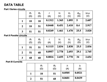
Transcribed Image Text:DATA TABLE
Part I Series circuits
1
2
3
Part II Parallel circuits
R₁
(Q)
151
2
3
R₁
(2)
10
10
51
Part III Currents
R₂
(Q)
10
51
51
R₂
(2)
51
51 68
68
68
1
2
R₁
(22)
10
51
1
V₁
V₂
(A)
(V) (V)
0.1312
1.365
0.0448
0.451
0.0249 1.461
1
(A)
0.1115
0.0957
0.0816 2.655
R₂
(Q)
51
68
1.095
2.410
1.470
Req
(22)
/1
(A)
0.0505
0.0601
5
8.4
V₁
V₂
Req
(V) (V)
(Q)
2.834
2.838
25.5
2.778 2.693 29.1
2.770
34
25.5
12
(A)
0.0521
0.0439
VTOT
(V)
2.607
2.917
3.020
VTOT
(V)
2.836
2.745
2.654
Expert Solution
This question has been solved!
Explore an expertly crafted, step-by-step solution for a thorough understanding of key concepts.
This is a popular solution
Trending nowThis is a popular solution!
Step by stepSolved in 4 steps with 1 images

Knowledge Booster
Learn more about
Need a deep-dive on the concept behind this application? Look no further. Learn more about this topic, electrical-engineering and related others by exploring similar questions and additional content below.Similar questions
- Q1- Determine the range of adjustable resistance, R. for a Wheatstone bridge circuit as shown in Figure Q1 that can measure voltage at range between 0 to 10 V. The voltage source is 50 V and fixed resistances, R1 = R2 = R3 = 1 K ohm, next, determine the range of current can be measured by using galvanometer with internal resistance is 200ohmarrow_forwardthe voltage that would be developed across a 50 ohm load connected to the terminals of a battery with 20 V no load terminal voltage and 5 ohm internal resistance is?arrow_forward
Recommended textbooks for you
 Introductory Circuit Analysis (13th Edition)Electrical EngineeringISBN:9780133923605Author:Robert L. BoylestadPublisher:PEARSON
 Delmar's Standard Textbook Of ElectricityElectrical EngineeringISBN:9781337900348Author:Stephen L. HermanPublisher:Cengage Learning
 Programmable Logic ControllersElectrical EngineeringISBN:9780073373843Author:Frank D. PetruzellaPublisher:McGraw-Hill Education
 Fundamentals of Electric CircuitsElectrical EngineeringISBN:9780078028229Author:Charles K Alexander, Matthew SadikuPublisher:McGraw-Hill Education
 Electric Circuits. (11th Edition)Electrical EngineeringISBN:9780134746968Author:James W. Nilsson, Susan RiedelPublisher:PEARSON
 Engineering ElectromagneticsElectrical EngineeringISBN:9780078028151Author:Hayt, William H. (william Hart), Jr, BUCK, John A.Publisher:Mcgraw-hill Education,

Introductory Circuit Analysis (13th Edition)
Electrical Engineering
ISBN:9780133923605
Author:Robert L. Boylestad
Publisher:PEARSON

Delmar's Standard Textbook Of Electricity
Electrical Engineering
ISBN:9781337900348
Author:Stephen L. Herman
Publisher:Cengage Learning

Programmable Logic Controllers
Electrical Engineering
ISBN:9780073373843
Author:Frank D. Petruzella
Publisher:McGraw-Hill Education

Fundamentals of Electric Circuits
Electrical Engineering
ISBN:9780078028229
Author:Charles K Alexander, Matthew Sadiku
Publisher:McGraw-Hill Education

Electric Circuits. (11th Edition)
Electrical Engineering
ISBN:9780134746968
Author:James W. Nilsson, Susan Riedel
Publisher:PEARSON

Engineering Electromagnetics
Electrical Engineering
ISBN:9780078028151
Author:Hayt, William H. (william Hart), Jr, BUCK, John A.
Publisher:Mcgraw-hill Education,