
Introductory Circuit Analysis (13th Edition)
13th Edition
ISBN: 9780133923605
Author: Robert L. Boylestad
Publisher: PEARSON
expand_more
expand_more
format_list_bulleted
Related questions
Concept explainers
Question
thumb_up100%
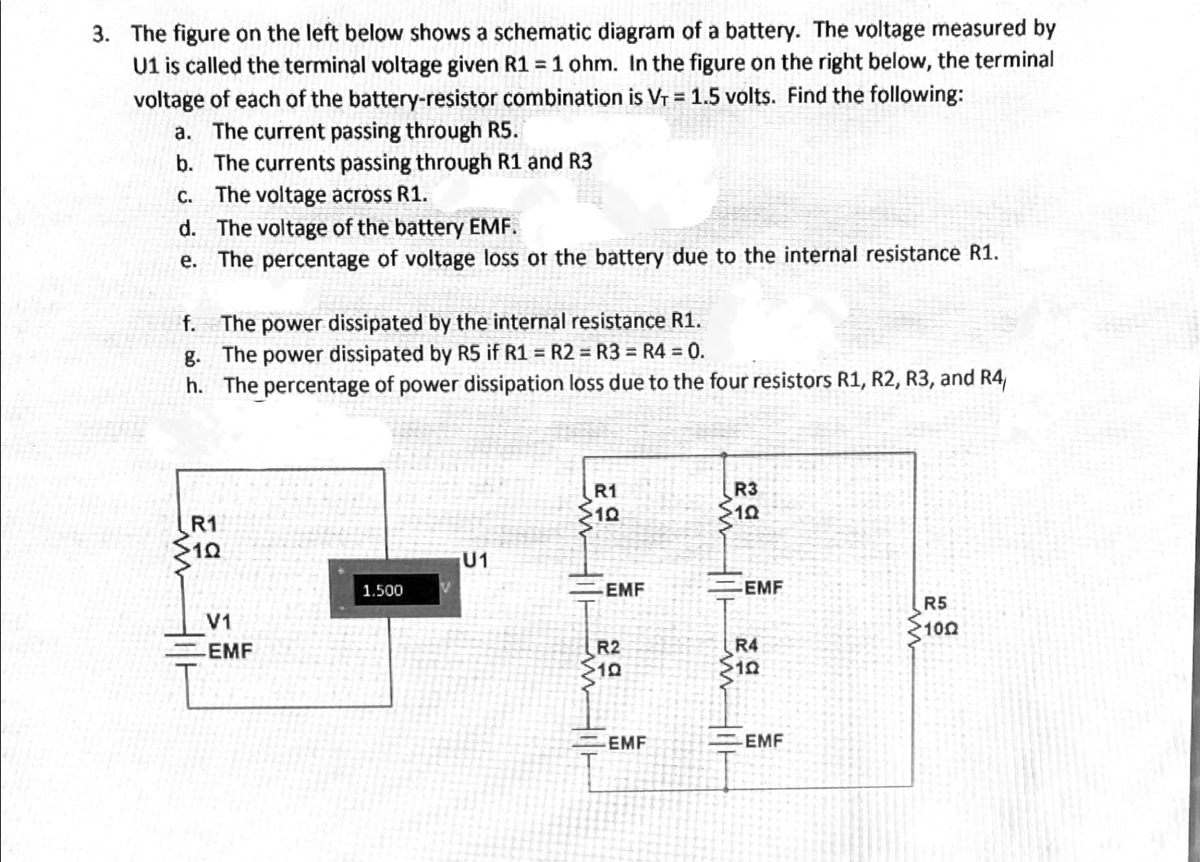

Transcribed Image Text:3. The figure on the left below shows a schematic diagram of a battery. The voltage measured by
U1 is called the terminal voltage given R1 = 1 ohm. In the figure on the right below, the terminal
voltage of each of the battery-resistor combination is Vr = 1.5 volts. Find the following:
a. The current passing through R5.
b. The currents passing through R1 and R3
C. The voltage across R1.
d. The voltage of the battery EMF.
e. The percentage of voltage loss ot the battery due to the internal resistance R1.
The power dissipated by the internal resistance R1.
g. The power dissipated by R5 if R1 = R2 = R3 = R4 = 0.
h. The percentage of power dissipation loss due to the four resistors R1, R2, R3, and R4
f.
R1
R3
S10
R1
U1
1.500
EMF
EMF
R5
100
V1
R2
$10
EMF
R4
EMF
EMF
Expert Solution
This question has been solved!
Explore an expertly crafted, step-by-step solution for a thorough understanding of key concepts.

This is a popular solution

Trending nowThis is a popular solution!

Step by stepSolved in 2 steps with 3 images

Knowledge Booster


Learn more about
Need a deep-dive on the concept behind this application? Look no further. Learn more about this topic, electrical-engineering and related others by exploring similar questions and additional content below.Similar questions
- Determine the followingarrow_forward2. A bank of nickel-cadmium cells is used as the emergency lighting supply for a hospital. There are 100 cells connected in series and each has an A-hr rating of 120 A-hr. The bank has to be replaced, and the manufacturer is no longer supplying nickel-cadmium cells. It is decided to replace the cells with lead-acid cells. How many lead-acid cells will be required if each has an A-hr rating of 60 A-hr, and how should they be connected?arrow_forwardA resistance of 10 ohms and C=0.1F is connected in series with a 12V battery. Find the charge at any time and the charge current 0.4 seconds after switch is closed.arrow_forward
- An example of Simple Resistive Circuits is ,arrow_forwardAsP plzzzzarrow_forwardCalculate the equivalent resistances Rin of the following circuits. (The resistance value of the diodes in the conduction will be 0, the resistance value of the diodes in the insulation will be taken as infinity. R1=10ohmarrow_forward
arrow_back_ios
arrow_forward_ios
Recommended textbooks for you
- Introductory Circuit Analysis (13th Edition)Electrical EngineeringISBN:9780133923605Author:Robert L. BoylestadPublisher:PEARSON
 Delmar's Standard Textbook Of ElectricityElectrical EngineeringISBN:9781337900348Author:Stephen L. HermanPublisher:Cengage Learning
 Programmable Logic ControllersElectrical EngineeringISBN:9780073373843Author:Frank D. PetruzellaPublisher:McGraw-Hill Education
  Fundamentals of Electric CircuitsElectrical EngineeringISBN:9780078028229Author:Charles K Alexander, Matthew SadikuPublisher:McGraw-Hill Education
 Electric Circuits. (11th Edition)Electrical EngineeringISBN:9780134746968Author:James W. Nilsson, Susan RiedelPublisher:PEARSON
 Engineering ElectromagneticsElectrical EngineeringISBN:9780078028151Author:Hayt, William H. (william Hart), Jr, BUCK, John A.Publisher:Mcgraw-hill Education,
Introductory Circuit Analysis (13th Edition)
Electrical Engineering
ISBN:9780133923605
Author:Robert L. Boylestad
Publisher:PEARSON
Delmar's Standard Textbook Of Electricity
Electrical Engineering
ISBN:9781337900348
Author:Stephen L. Herman
Publisher:Cengage Learning
Programmable Logic Controllers
Electrical Engineering
ISBN:9780073373843
Author:Frank D. Petruzella
Publisher:McGraw-Hill Education
Fundamentals of Electric Circuits
Electrical Engineering
ISBN:9780078028229
Author:Charles K Alexander, Matthew Sadiku
Publisher:McGraw-Hill Education
Electric Circuits. (11th Edition)
Electrical Engineering
ISBN:9780134746968
Author:James W. Nilsson, Susan Riedel
Publisher:PEARSON
Engineering Electromagnetics
Electrical Engineering
ISBN:9780078028151
Author:Hayt, William H. (william Hart), Jr, BUCK, John A.
Publisher:Mcgraw-hill Education,