Introductory Circuit Analysis (13th Edition)
13th Edition
ISBN: 9780133923605
Author: Robert L. Boylestad
Publisher: PEARSON
expand_more
expand_more
format_list_bulleted
Question

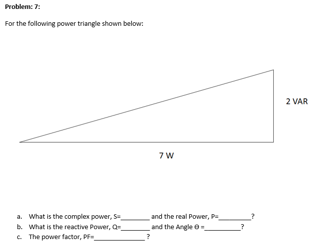
Transcribed Image Text:a. What is the complex power, S=
b. What is the reactive Power, Q=.
c. The power factor, PF=
and the real Power, P=
and the Angle e =
Expert Solution
This question has been solved!
Explore an expertly crafted, step-by-step solution for a thorough understanding of key concepts.
This is a popular solution
Trending nowThis is a popular solution!
Step by stepSolved in 4 steps with 9 images

Knowledge Booster
Learn more about
Need a deep-dive on the concept behind this application? Look no further. Learn more about this topic, electrical-engineering and related others by exploring similar questions and additional content below.Similar questions
- Component values of the following circuit are listed in the Table I. Answer the following questions and provide your answers in Table II. a) find amplitude and phase of Vout? Table I. Components (0 1 [rad/s] C₁ V₁ 1 40° Vout L₁ 1 [H] L₂ 4 [H] L₂ ooo C₁ 2 [F] C₂ C₂ Vin 0.5 [F] Table II. Answer + Voutarrow_forwardWhat are the input and output impedances for the circuit shown in the figure?arrow_forwardIn a series R–L circuit the p.d. across the resistance R is 12V and the p.d. across the inductance L is 5V. Find the supply voltage and the phase angle between current and voltagearrow_forward
- This isn't apart of a test it is a homework question I added an image that contains the figure for this problem An RLC��� circuit with a 15 μF�F capacitor is connected to a variable-frequency power supply with an rms output voltage of 6.8 VV . The rms current in the circuit as a function of the driving frequency appears as in (Figure 1) . Part A What is the value of the resistor? Express your answer to two significant figures and include the appropriate units. figure 1 image for this question. Question 2 John is changing a lightbulb in a lamp. It's a warm summer evening, and the resistance of his damp skin is only 3300 ΩΩ . While one hand is holding the grounded metal frame of the lamp, the other hand accidentally touches the hot electrode in the base of the socket. The voltage of the socket is 120 VV . Use the data shown in (Figure 1) . Part A What is the current through his torso? Express your answer with the appropriate units.arrow_forwardA load has 50 kw active power with 0.8 power factor to make load power factor with 0.9 power factor. How much reactive power should be supplied by capacitor.arrow_forwardA 555 Timer has a frequency of 200HZ at the output. The capacitance used is 5nF. Replace the capacitance value so that we decrease the frequency to 20Hz. Write your answer in nF: nFarrow_forward
- What is the power factor for the circuit in the figure below? Given: R = 250 0, L = 750 mH 120 v 60 Hz Select one: a. 66.3 % O b. 89.7 % O c. 92.6 % O d. 151 % Rarrow_forwardA 15µF capacitor and a 470 ohm resistor are connected in series with a function generator. The supply voltage is 50V RMS 40Hz. Find the reactive power for this circuit.arrow_forward12. Derive the following. Assume an ideal current source a. frequency response b. input impedance c. output impedance T V DD bias C.arrow_forward
- The circuit in the figure is supplied with a sinusoidal alternating voltage. a) Calculate the source voltage U. c) Calculate the active power d) Determine the impedance of the circuitarrow_forwardQUESTION 6 P 0.8 pf lagging For the circuit shown above, what is the input power factor angle? Assume that is = 7 + j0 A, P₁ = 278 W, and P2 = 124 W. Write your answer in degrees. + To P 0.9 pf laggingarrow_forwardComponent values of the following circuit are listed in the Table I. Answer the following questions and provide your answers in Table II. a) find amplitude and phase of Vout? Table I. Components (0 1 [rad/s] C₁ V₁ Vout L₁ L₂ L₂ voo C₁ Vin C₂ C₂ Table II. Answer + Vout 1 40° 1 [H] 4 [H] 2 [F] 0.5 [F]arrow_forward
arrow_back_ios
SEE MORE QUESTIONS
arrow_forward_ios
Recommended textbooks for you
 Introductory Circuit Analysis (13th Edition)Electrical EngineeringISBN:9780133923605Author:Robert L. BoylestadPublisher:PEARSON
 Delmar's Standard Textbook Of ElectricityElectrical EngineeringISBN:9781337900348Author:Stephen L. HermanPublisher:Cengage Learning
 Programmable Logic ControllersElectrical EngineeringISBN:9780073373843Author:Frank D. PetruzellaPublisher:McGraw-Hill Education
 Fundamentals of Electric CircuitsElectrical EngineeringISBN:9780078028229Author:Charles K Alexander, Matthew SadikuPublisher:McGraw-Hill Education
 Electric Circuits. (11th Edition)Electrical EngineeringISBN:9780134746968Author:James W. Nilsson, Susan RiedelPublisher:PEARSON
 Engineering ElectromagneticsElectrical EngineeringISBN:9780078028151Author:Hayt, William H. (william Hart), Jr, BUCK, John A.Publisher:Mcgraw-hill Education,

Introductory Circuit Analysis (13th Edition)
Electrical Engineering
ISBN:9780133923605
Author:Robert L. Boylestad
Publisher:PEARSON

Delmar's Standard Textbook Of Electricity
Electrical Engineering
ISBN:9781337900348
Author:Stephen L. Herman
Publisher:Cengage Learning

Programmable Logic Controllers
Electrical Engineering
ISBN:9780073373843
Author:Frank D. Petruzella
Publisher:McGraw-Hill Education

Fundamentals of Electric Circuits
Electrical Engineering
ISBN:9780078028229
Author:Charles K Alexander, Matthew Sadiku
Publisher:McGraw-Hill Education

Electric Circuits. (11th Edition)
Electrical Engineering
ISBN:9780134746968
Author:James W. Nilsson, Susan Riedel
Publisher:PEARSON

Engineering Electromagnetics
Electrical Engineering
ISBN:9780078028151
Author:Hayt, William H. (william Hart), Jr, BUCK, John A.
Publisher:Mcgraw-hill Education,