
Steel Design (Activate Learning with these NEW titles from Engineering!)
6th Edition
ISBN: 9781337094740
Author: Segui, William T.
Publisher: Cengage Learning
expand_more
expand_more
format_list_bulleted
Related questions
Question
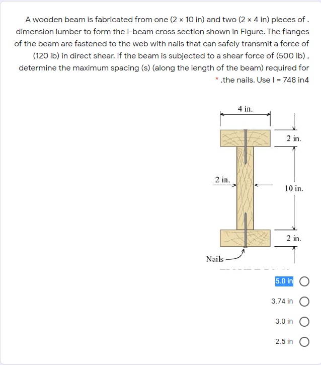

Transcribed Image Text:A wooden beam is fabricated from one (2 x 10 in) and two (2 x 4 in) pieces of .
dimension lumber to form the l-beam cross section shown in Figure. The flanges
of the beam are fastened to the web with nails that can safely transmit a force of
(120 Ib) in direct shear. If the beam is subjected to a shear force of (50O Ib),
determine the maximum spacing (s) (along the length of the beam) required for
* .the nails. Usel = 748 in4
4 in.
2 in.
2 in.
10 in.
2 in.
Nails
5.0 in O
3.74 in
3.0 in O
2.5 in
Expert Solution
This question has been solved!
Explore an expertly crafted, step-by-step solution for a thorough understanding of key concepts.

This is a popular solution

Trending nowThis is a popular solution!

Step by stepSolved in 4 steps

Knowledge Booster


Learn more about
Need a deep-dive on the concept behind this application? Look no further. Learn more about this topic, civil-engineering and related others by exploring similar questions and additional content below.Similar questions
- Compute the nominal shear strength of an M107.5 of A572 Grad 65 steel.arrow_forwardCompute the nominal shear strength of an M1211.8 of A572 Grade 65 steel.arrow_forwardDetermine the smallest value of yield stress Fy, for which a W-, M-, or S-shape from Part 1 of the Manual will become slender. To which shapes does this value apply? What conclusion can you draw from your answer?arrow_forward
- Use the composite beam tables and select a W-shape and stud anchors for the following conditions: Span length = 18 6 Beam spacing = 9 ft Total slab thickness = 51 2 in. (the slab and deck combination weighs 57 psf). Lightweight concrete with a unit weight of 115 pcf is used Construction load = 20 psf Partition load = 20 psf Live load = 225 psf Fy=50 ksi and fc=4 ksi A cross section of the formed steel deck is shown in Figure P9.8-9. The maximum live-load deflection cannot exceed L/360 (use a lower-bound moment of inertia). a. Use LRFD. b. User ASD.arrow_forwardA W1422 acts compositely with a 4-inch-thick floor slab whose effective width b is 90 inches. The beams are spaced at 7 feet 6 inches, and the span length is 30 feet. The superimposed loads are as follows: construction load = 20 psf, partition load = 10 psf, weight of ceiling and light fixtures = 5 psf, and live load = 60 psf, A992 steel is used, and fc=4 ksi. Determine whether the flexural strength is adequate. a. Use LRFD. b. Use ASD.arrow_forwardEstimate the transverse tensile strength of the concrete in Problem 12.6.arrow_forward
- A tensile test was performed on a metal specimen having a circular cross section with a diameter 0. 510 inch. For each increment of load applied, the strain was directly determined by means of a strain gage attached to the specimen. The results are, shown in Table: 1.5.1. a. Prepare a table of stress and strain. b. Plot these data to obtain a stress-strain curve. Do not connect the data points; draw a best-fit straight line through them. c. Determine the modulus of elasticity as the slope of the best-fit line.arrow_forwardThe data in Table 1.5.3 were obtained from a tensile test of a metal specimen with a rectangular cross section of 0.2011in.2 in area and a gage length (the length over which the elongation is measured) of 2.000 inches. The specimen was not loaded to failure. a. Generate a table of stress and strain values. b. Plot these values and draw a best-fit line to obtain a stress-strain curve. c. Determine the modulus of elasticity from the slope of the linear portion of the curve. d. Estimate the value of the proportional limit. e. Use the 0.2 offset method to determine the yield stress.arrow_forwardA beam is part of the framing system for the floor of an office building. The floor is subjected to both dead loads and live loads. The maximum moment caused by the service dead load is 45 ft-kips, and the maximum moment for the service live load is 63 ft-kips (these moments occur at the same location on the beam and can therefore be combined). a. If load and resistance factor design is used, determine the maximum factored bending moment (required moment strength). What is the controlling AISC load combination? b. What is the required nominal moment strength for a resistance factor of 0.90? c. If allowable strength design is used, determine the required moment strength. What is the controlling AISC lead combination? d. What is the required nominal moment strength for a safety factor of 1.67?arrow_forward
- Use an elastic analysis and determine the maximum load in the weld (in kips per inch of length).arrow_forwardA plate girder must be designed for the conditions shown in Figure P10.7-4. The given loads are factored, and the uniformly distributed load includes a conservative estimate of the girder weight. Lateral support is provided at the ands and at the load points. Use LRFD for that following: a. Select the, flange and web dimensions so that intermediate stiffeners will he required. Use Fy=50 ksi and a total depth of 50 inches. Bearing stiffeners will be used at the ends and at the load points, but do not proportion them. b. Determine the locations of the intermediate stiffeners, but do not proportion them.arrow_forwardA beam must be designed to the following specifications: Span length = 35 ft Beam spacing = 10 ft 2-in. deck with 3 in. of lightweight concrete fill (wc=115 pcf) for a total depth of t=5 in. Total weight of deck and slab = 51 psf Construction load = 20 psf Partition load = 20 psf Miscellaneous dead load = 10 psf Live load = 80 psf Fy=50 ksi, fc=4 ksi Assume continuous lateral support and use LRFD. a. Design a noncomposite beam. Compute the total deflection (there is no limit to be checked). b. Design a composite beam and specify the size and number of stud anchors required. Assume one stud at each beam location. Compute the maximum total deflection as follows: 1. Use the transformed section. 2. Use the lower-bound moment of inertia.arrow_forward
arrow_back_ios
arrow_forward_ios
Recommended textbooks for you
- Steel Design (Activate Learning with these NEW ti...Civil EngineeringISBN:9781337094740Author:Segui, William T.Publisher:Cengage Learning
 Materials Science And Engineering PropertiesCivil EngineeringISBN:9781111988609Author:Charles GilmorePublisher:Cengage Learning
 Construction Materials, Methods and Techniques (M...Civil EngineeringISBN:9781305086272Author:William P. Spence, Eva KultermannPublisher:Cengage Learning
Steel Design (Activate Learning with these NEW ti...
Civil Engineering
ISBN:9781337094740
Author:Segui, William T.
Publisher:Cengage Learning
Materials Science And Engineering Properties
Civil Engineering
ISBN:9781111988609
Author:Charles Gilmore
Publisher:Cengage Learning
Construction Materials, Methods and Techniques (M...
Civil Engineering
ISBN:9781305086272
Author:William P. Spence, Eva Kultermann
Publisher:Cengage Learning