Introductory Circuit Analysis (13th Edition)
13th Edition
ISBN: 9780133923605
Author: Robert L. Boylestad
Publisher: PEARSON
expand_more
expand_more
format_list_bulleted
Question

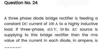
Transcribed Image Text:Question No. 24
A three phase diode bridge rectifier is feeding a
constant DC current of 100 A to a highly inductive
load. If three-phase, 415 V, 50 Hz AC source is
supplying to this bridge rectifier then the rms
value of the current in each diode, in ampere, is
Expert Solution
This question has been solved!
Explore an expertly crafted, step-by-step solution for a thorough understanding of key concepts.
Step by stepSolved in 2 steps with 2 images

Knowledge Booster
Learn more about
Need a deep-dive on the concept behind this application? Look no further. Learn more about this topic, electrical-engineering and related others by exploring similar questions and additional content below.Similar questions
- LR phase shift control is used in a controlled rectifier. If the value of the inductor is 100 mH, find the minimum and maximum value of the control resistor if the ratio of Idc/Idcmax is to be 0.1 to 0.9.arrow_forwardH.W4 The diode in the single-phase half wave rectifier has a reverse recovery time of tr frequency = 5 kHz. 150usec and the source voltage V₁ = 200V at Calculate the average output voltage. EParrow_forwardIn the following circuit, Vin is a sinusoid AC input voltage which has a 5. peak voltage of 15v. Zener diode D has a Zener voltage of 10V. Sketch the waveform of Vout. Hint: Consider when Zener diode is forward and reverse biased. R 1ka Vin Voutarrow_forward
- Topic: Half Wave Rectificationarrow_forwardSketch the output waveform and indicate the expected voltage levels for each of these diode circuits below. Use the diode models as indicated.arrow_forwardIn the single-phase half-wave diode rectifier with an inductive load, if the inductor starts discharging its energy and continuous until 205 degrees, the value of inversion conduction-angle of a diode is:arrow_forward
- The four diodes used in a bridge rectifier circuit have forward resistances which may be considered constant at 1 ohm and infinite reverse resistance. The alternating supply voltage is 220 V r.m.s. and load resistance is 580 ohm. Calculate (i) mean load current and (ii) power dissipated in each diode.arrow_forwardAnswer a,b,c,darrow_forward
arrow_back_ios
arrow_forward_ios
Recommended textbooks for you
 Introductory Circuit Analysis (13th Edition)Electrical EngineeringISBN:9780133923605Author:Robert L. BoylestadPublisher:PEARSON
 Delmar's Standard Textbook Of ElectricityElectrical EngineeringISBN:9781337900348Author:Stephen L. HermanPublisher:Cengage Learning
 Programmable Logic ControllersElectrical EngineeringISBN:9780073373843Author:Frank D. PetruzellaPublisher:McGraw-Hill Education
 Fundamentals of Electric CircuitsElectrical EngineeringISBN:9780078028229Author:Charles K Alexander, Matthew SadikuPublisher:McGraw-Hill Education
 Electric Circuits. (11th Edition)Electrical EngineeringISBN:9780134746968Author:James W. Nilsson, Susan RiedelPublisher:PEARSON
 Engineering ElectromagneticsElectrical EngineeringISBN:9780078028151Author:Hayt, William H. (william Hart), Jr, BUCK, John A.Publisher:Mcgraw-hill Education,

Introductory Circuit Analysis (13th Edition)
Electrical Engineering
ISBN:9780133923605
Author:Robert L. Boylestad
Publisher:PEARSON

Delmar's Standard Textbook Of Electricity
Electrical Engineering
ISBN:9781337900348
Author:Stephen L. Herman
Publisher:Cengage Learning

Programmable Logic Controllers
Electrical Engineering
ISBN:9780073373843
Author:Frank D. Petruzella
Publisher:McGraw-Hill Education

Fundamentals of Electric Circuits
Electrical Engineering
ISBN:9780078028229
Author:Charles K Alexander, Matthew Sadiku
Publisher:McGraw-Hill Education

Electric Circuits. (11th Edition)
Electrical Engineering
ISBN:9780134746968
Author:James W. Nilsson, Susan Riedel
Publisher:PEARSON

Engineering Electromagnetics
Electrical Engineering
ISBN:9780078028151
Author:Hayt, William H. (william Hart), Jr, BUCK, John A.
Publisher:Mcgraw-hill Education,