Introductory Circuit Analysis (13th Edition)
13th Edition
ISBN: 9780133923605
Author: Robert L. Boylestad
Publisher: PEARSON
expand_more
expand_more
format_list_bulleted
Question

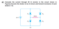
Transcribed Image Text:Q*: Calculate the current through 48 Q resistor in the circuit shown in
Figure(i).Assume the diodes to be of silicon and forward resistance of each
diode is 1 Q.
D
D2
48 2
ww
10 V=
D4
D3
(i)
Expert Solution
This question has been solved!
Explore an expertly crafted, step-by-step solution for a thorough understanding of key concepts.
This is a popular solution
Trending nowThis is a popular solution!
Step by stepSolved in 2 steps with 4 images

Knowledge Booster
Learn more about
Need a deep-dive on the concept behind this application? Look no further. Learn more about this topic, electrical-engineering and related others by exploring similar questions and additional content below.Similar questions
- Q1arrow_forwardCalculate the current flowing through the given circuit and the voltage value at the V0 ends. (Threshold voltage = 0.3V for Germanium diodes, Threshold voltage for silicon diodes = 0.6V)arrow_forwardIn the circuit below, sinusoidal input voltage with a peak value of 10V is applied. Calculate the current flowing through the diodes D1 and D2 by drawing the waveform of the output voltage. (Both diodes will be considered ideal and Vc=5V).arrow_forward
- 1 Draw the output waveform of the following Clamper’s circuits while the input is given below and biasing voltage (V=5v) is 5 v. Practical silicon diode is to be considered for analysis to draw output waveform.arrow_forwardConsider the following circuit: VI R₁ = 4kQ2 IDI R₂ = 8 ΚΩ D₁ ID2 R3 = 6 ΚΩ D2 ID3 + 1.0 V - VO R4= 4 ΚΩ D3 + 2.0 V Figure 1: Diode circuit for the Question Please find Ip1, ID2, IDs and to using constant voltage drop model for diodes. UF 0.7 V. v1 = 3V.arrow_forwardA zener diode exhibits a certain change in VZ for a certain change in IZ on a portion of the linear characteristic curve between IZK and IZM as illustrated in Figure 5. Calculate the zener impedance.arrow_forward
- In figure (a) the conducting diode is: a, b or c?arrow_forwardThese are subparts of a question so please answer all and dont palagarizearrow_forwardIn a single phase half wave controlled rectifier with inductive load without freewheeling diode, the output voltage is zero during the wt=t to 2rt. Select one: O True O Falsearrow_forward
- Power supply circuit is delivering 0.5 A and an average voltage 20 V to the load as shown in the circuit below. The ripple voltage of the half wave rectifier is 0.5 V and the diode is represented using constant voltage model. The smoothing capacitor value is equal to IL-DC =0:5A RL VL-DC =20V 220V omsb O 001 F O 0.02 F O 0.0167F O None of the above Activatearrow_forwardThe thickness of the PN depletion region increases when diode is Your answer The function of zener diode is to provide a constant output voltage to a load. this process is called Your answer One types of diodes are typically used for power supply applications which always called Your answerarrow_forwardPlease show your complete solution on how to find the missing values. I want to learn how to solve this problem. Thank you.arrow_forward
arrow_back_ios
SEE MORE QUESTIONS
arrow_forward_ios
Recommended textbooks for you
 Introductory Circuit Analysis (13th Edition)Electrical EngineeringISBN:9780133923605Author:Robert L. BoylestadPublisher:PEARSON
 Delmar's Standard Textbook Of ElectricityElectrical EngineeringISBN:9781337900348Author:Stephen L. HermanPublisher:Cengage Learning
 Programmable Logic ControllersElectrical EngineeringISBN:9780073373843Author:Frank D. PetruzellaPublisher:McGraw-Hill Education
 Fundamentals of Electric CircuitsElectrical EngineeringISBN:9780078028229Author:Charles K Alexander, Matthew SadikuPublisher:McGraw-Hill Education
 Electric Circuits. (11th Edition)Electrical EngineeringISBN:9780134746968Author:James W. Nilsson, Susan RiedelPublisher:PEARSON
 Engineering ElectromagneticsElectrical EngineeringISBN:9780078028151Author:Hayt, William H. (william Hart), Jr, BUCK, John A.Publisher:Mcgraw-hill Education,

Introductory Circuit Analysis (13th Edition)
Electrical Engineering
ISBN:9780133923605
Author:Robert L. Boylestad
Publisher:PEARSON

Delmar's Standard Textbook Of Electricity
Electrical Engineering
ISBN:9781337900348
Author:Stephen L. Herman
Publisher:Cengage Learning

Programmable Logic Controllers
Electrical Engineering
ISBN:9780073373843
Author:Frank D. Petruzella
Publisher:McGraw-Hill Education

Fundamentals of Electric Circuits
Electrical Engineering
ISBN:9780078028229
Author:Charles K Alexander, Matthew Sadiku
Publisher:McGraw-Hill Education

Electric Circuits. (11th Edition)
Electrical Engineering
ISBN:9780134746968
Author:James W. Nilsson, Susan Riedel
Publisher:PEARSON

Engineering Electromagnetics
Electrical Engineering
ISBN:9780078028151
Author:Hayt, William H. (william Hart), Jr, BUCK, John A.
Publisher:Mcgraw-hill Education,