Structural Analysis
6th Edition
ISBN: 9781337630931
Author: KASSIMALI, Aslam.
Publisher: Cengage,
expand_more
expand_more
format_list_bulleted
Question
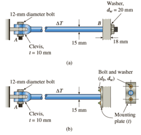
- A steel rod of 15- mm diameter is held snugly (but without any initial stresses) between rigid walls by the arrangement shown in the figure part (a). (For the steel rod, use α = 12 x 10-6/˚C and E = 200 GPa.)
- Calculate the temperature drop ΔT (degrees Celsius) at which the average shear stress in the 12 – mm diameter bolt becomes 45 MPa. Also, what is the normal stress in the rod?
- What are the average bearing stresses in the bolt and clevis at A and between the washer (dW = 20mm) and wall (t = 18 mm) at B?
- If the connection to the wall at B is changed to an end plate with two bolts (see figure part b), what is the required diameter db of each bolt if the temperature drop is ΔT = 38˚C and the allowable bolt stress is 90 MPa?

Transcribed Image Text:12-mm diameter bolt
Clevis,
1 = 10 mm
12-mm diameter bolt
Clevis,
t = 10 mm
AT
AT
15 mm
(a)
15 mm
(b)
B
Washer,
dw = 20 mm
18 mm
Bolt and washer
(dy, dw)
P00
Mounting
plate (1)
Expert Solution
This question has been solved!
Explore an expertly crafted, step-by-step solution for a thorough understanding of key concepts.
This is a popular solution
Trending nowThis is a popular solution!
Step by stepSolved in 4 steps with 4 images

Knowledge Booster
Learn more about
Need a deep-dive on the concept behind this application? Look no further. Learn more about this topic, civil-engineering and related others by exploring similar questions and additional content below.Similar questions
- A solid brass shaft is loaded as shown below by two torques TB= 1100 Nm and TC= 400 Nm. The lengths of the two segments are LAB= 750 mm and LBC= 600 mm. For brass, G = 41 GPa. Neglect the effect of any stress concentrations. Determine the smallest diameters dAB and dBC for which an allowable shear stress of 60 MPa is not exceeded. Express each diameter as an integer in units of mm.arrow_forwardThe assembly shown in figure below consists of a light rigid bar AB, pinned at O, that is attached to the steel and aluminum rods. In the position shown, bar AB is horizontal and there is a gap, A = 5 mm, between the lower end of the steel rod and its pin support at C. Compute the stress in the aluminum rod when the lower end of the steel rod is touch to its support. A 0.75 m Steel A = 250 mm E = 200 GPa *i* O 1.5 m Aluminum L = 2m A = 300 mm' E = 70 GPa B Darrow_forwardA steel pipe is subjected to the 16-kN load shown below. Its outside diameter is 140 mm and its thickness is 7 mm. Consider that the yield strength of steel is 240 MPa. Analyze point H ONLY. Due to the pressure in the pipe, there is an 11.25-MPa (T) normal stress along x and a 22.50-MPa (T) normal stress along z of point H. A. Determine the internal forces and moments at the pertinent section through an FBD. B. Determine the stresses experienced by point H. Illustrate using a stress element. C. Determine the FS by MSST at point H D. Determine the von Mises equivalent stress at point H E. Determine the FS by MDET at point H 700 mm 16 KN 1,300 mmarrow_forward
- Maximum allowable (safe) bending stress for a beam AB under a constant distributed load as shown in the figure.It is 40 MPa.a) What is the maximum value of the length (L) of the beam in this case?b) Draw the shear stress (τ) profile where the V (shear in section) force is greatest.Hint: You can specify several points in the section and calculate the shear stress for those points.arrow_forward6- A circular shaft is composed of a steel core and a brass covering, as shown in the figure. Under the applied torque, what is the maximum shear stress in each material? The composite shaft is attached to a wall at A. B O T= 5 KN•m Steel core r=15mm G=78 GPa bross cylinder ro=20mm (outer diameter) G=39 GPaarrow_forwardplease just solve the second partarrow_forward
arrow_back_ios
arrow_forward_ios
Recommended textbooks for you

 Structural Analysis (10th Edition)Civil EngineeringISBN:9780134610672Author:Russell C. HibbelerPublisher:PEARSON
 Principles of Foundation Engineering (MindTap Cou...Civil EngineeringISBN:9781337705028Author:Braja M. Das, Nagaratnam SivakuganPublisher:Cengage Learning
 Fundamentals of Structural AnalysisCivil EngineeringISBN:9780073398006Author:Kenneth M. Leet Emeritus, Chia-Ming Uang, Joel LanningPublisher:McGraw-Hill Education
 Traffic and Highway EngineeringCivil EngineeringISBN:9781305156241Author:Garber, Nicholas J.Publisher:Cengage Learning


Structural Analysis (10th Edition)
Civil Engineering
ISBN:9780134610672
Author:Russell C. Hibbeler
Publisher:PEARSON

Principles of Foundation Engineering (MindTap Cou...
Civil Engineering
ISBN:9781337705028
Author:Braja M. Das, Nagaratnam Sivakugan
Publisher:Cengage Learning

Fundamentals of Structural Analysis
Civil Engineering
ISBN:9780073398006
Author:Kenneth M. Leet Emeritus, Chia-Ming Uang, Joel Lanning
Publisher:McGraw-Hill Education


Traffic and Highway Engineering
Civil Engineering
ISBN:9781305156241
Author:Garber, Nicholas J.
Publisher:Cengage Learning