
Structural Analysis
6th Edition
ISBN: 9781337630931
Author: KASSIMALI, Aslam.
Publisher: Cengage,
expand_more
expand_more
format_list_bulleted
Related questions
Question
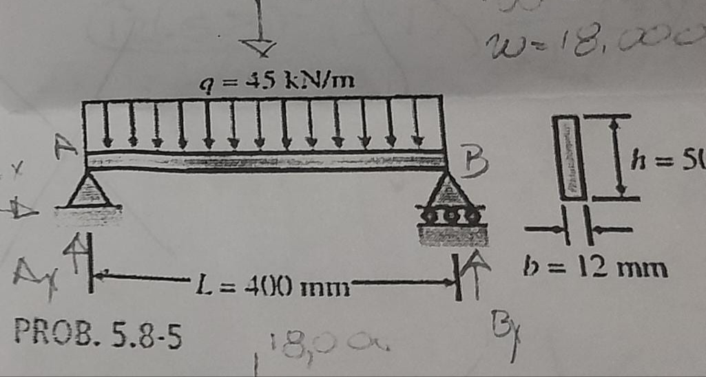
A steel beam with length L = 400 mm and transverse dimensions b = 12 mm and h = 50 mm (see the figure) supports a uniform load with intensity q = 45kN/m which includes the weight of the beam. Calculate the shear stresses in the beam (at the maximum shear cross section). at points located 6.25 mm, 12.5 mm, 18.75 mm and 25 mm from the top surface of the beam. From these calculations, make a graph showing the distribution of shear stresses from the top to the bottom of the beam.

Transcribed Image Text:Ax the
H
PROB. 5.8-5
9 = 45 kN/m
L=400 mm
18,00
W= 18,000
II
h = SU
* b = 12 mm
By
Expert Solution
This question has been solved!
Explore an expertly crafted, step-by-step solution for a thorough understanding of key concepts.

Step by stepSolved in 6 steps with 9 images

Knowledge Booster


Learn more about
Need a deep-dive on the concept behind this application? Look no further. Learn more about this topic, civil-engineering and related others by exploring similar questions and additional content below.Similar questions
- Help me urgent Two forces are applied ti the bar shown in the figure. Determine the normal and shearing stresses at point A, B and C?arrow_forwardA 52-kip force acts on a machine part at point A as shown below. The diagram shows the internal normal force, shear force and bending moment acting on a particular RECTANGULAR Cross section. -30in N 10in 26in F=52 kip The value of the bending moment M you would use to find the bending stress on a stress element located 2 inches up from the bottom of the rectangular cross section is closest to: 264 kip-in O a. 408 kip-in Ob. 1,464 kip-in O c. 1,608 kip-inarrow_forwardC. A rigid steel bar is suspended horizontally by 1m steel rod at one end and 2m bronze rod at the other end as shown. Neglecting the mass of the steel bar, at what distance X (in meters) from the steel rod should a 20 kN force be placed so that the steel bar will remain horizontal? Also, calculate the stresses in steel and bronze rod (in MPa). Use the following data. Steel, st Bronze, Br Br. 2m 20000 N Area (mm²) 600 300 St. 1m -X- E(GPa) 200 83 10 marrow_forward
- A steel specimen of 12 mm diameter extends by 6.31 x 10⁻² mm over a gauge length of 150 mm when subjected to an axial load of 10 kN. The same specimen undergoes a twist of 0.5° an a length of 150 mm over a twisting moment of 10 N-m. Using the above data, determine the elastic constants E, Mu, G and K.arrow_forwardCalculate the design moment strength Mu for the following section. Take f'c = 40 MPa. Sketch the strain and stress distribution diagrams for each section and try to work out your solutions using equilibrium conditions. Yield stress for N bars is 500 MPa. 75 700 60 1500 T 4N28 450arrow_forward
arrow_back_ios
arrow_forward_ios
Recommended textbooks for you
 Structural Analysis (10th Edition)Civil EngineeringISBN:9780134610672Author:Russell C. HibbelerPublisher:PEARSON
 Principles of Foundation Engineering (MindTap Cou...Civil EngineeringISBN:9781337705028Author:Braja M. Das, Nagaratnam SivakuganPublisher:Cengage Learning
 Fundamentals of Structural AnalysisCivil EngineeringISBN:9780073398006Author:Kenneth M. Leet Emeritus, Chia-Ming Uang, Joel LanningPublisher:McGraw-Hill Education
 Traffic and Highway EngineeringCivil EngineeringISBN:9781305156241Author:Garber, Nicholas J.Publisher:Cengage Learning
Structural Analysis (10th Edition)
Civil Engineering
ISBN:9780134610672
Author:Russell C. Hibbeler
Publisher:PEARSON
Principles of Foundation Engineering (MindTap Cou...
Civil Engineering
ISBN:9781337705028
Author:Braja M. Das, Nagaratnam Sivakugan
Publisher:Cengage Learning
Fundamentals of Structural Analysis
Civil Engineering
ISBN:9780073398006
Author:Kenneth M. Leet Emeritus, Chia-Ming Uang, Joel Lanning
Publisher:McGraw-Hill Education
Traffic and Highway Engineering
Civil Engineering
ISBN:9781305156241
Author:Garber, Nicholas J.
Publisher:Cengage Learning