Elements Of Electromagnetics
7th Edition
ISBN: 9780190698614
Author: Sadiku, Matthew N. O.
Publisher: Oxford University Press
expand_more
expand_more
format_list_bulleted
Concept explainers
Question

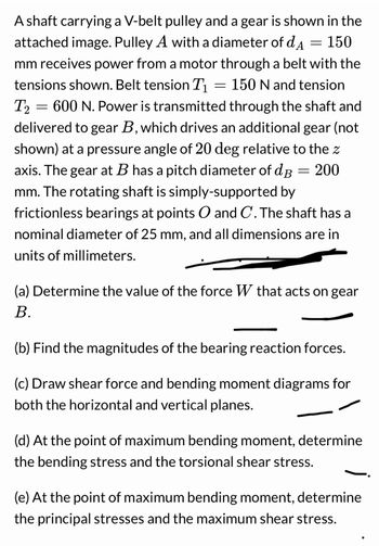
Transcribed Image Text:A shaft carrying a V-belt pulley and a gear is shown in the
attached image. Pulley A with a diameter of d = 150
mm receives power from a motor through a belt with the
tensions shown. Belt tension T₁ = 150 N and tension
T2 = 600 N. Power is transmitted through the shaft and
delivered to gear B, which drives an additional gear (not
shown) at a pressure angle of 20 deg relative to the z
axis. The gear at B has a pitch diameter of dB = 200
mm. The rotating shaft is simply-supported by
frictionless bearings at points O and C. The shaft has a
nominal diameter of 25 mm, and all dimensions are in
units of millimeters.
(a) Determine the value of the force W that acts on gear
B.
(b) Find the magnitudes of the bearing reaction forces.
(c) Draw shear force and bending moment diagrams for
both the horizontal and vertical planes.
(d) At the point of maximum bending moment, determine
the bending stress and the torsional shear stress.
(e) At the point of maximum bending moment, determine
the principal stresses and the maximum shear stress.

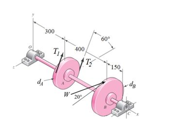
Transcribed Image Text:300
d₁
T₁
W
400
20°
T₂
60°
B
150
dB
Expert Solution
This question has been solved!
Explore an expertly crafted, step-by-step solution for a thorough understanding of key concepts.
This is a popular solution
Trending nowThis is a popular solution!
Step by stepSolved in 6 steps with 8 images

Knowledge Booster
Learn more about
Need a deep-dive on the concept behind this application? Look no further. Learn more about this topic, mechanical-engineering and related others by exploring similar questions and additional content below.Similar questions
- Q-5 A shaft carries four masses in parallel planes A, B, C and D in this order along its length. The masses at B and C are 18 kg and 12.5 kg respectively, and each has an eccentricity of 60 mm. The masses at A and D have an eccentricity of 80 mm. The angle between the masses at B and C is 100° and that between the masses at B and A is 190°, both being measured in the same direction. The axial distance between the planes A and B is 100 mm and that between B and C is 200 mm. If the shaft is in complete dynamic balance, determine: 1. The magnitude of the masses at A and D; 2. the distance between planes A and D; and 3. the angular position of the mass at D.arrow_forwardEx. #5] Pinion 2 in the figure runs at 1 750 rpm and transmits 2.5 kW to idler gear 3. The teeth are cut on the 20° full-depth system and have a module of m= 2.5 mm. Draw the free body diagram of gear 3 and shows all the forces acting upon it. Determine the forces acting upon gear 3. The direction of rotation of gear 3, as shown, is counterclockwise. GIVEN: Figure shown N₂ = 1750 rpm $=200 P = 2.5 kW m = 2.5 mm 3 0₂ REQUIRED: CS Draw the freehody diagram of gear 3 and compute the forces acting on it.arrow_forwardIn the image on the right, there is a red gear G1 on the left with a radius of r1 = 2.81cm. Gear G1 is locked to the green gear G2 with a radius of r2 = 0.734cm. Gear G2 then shares the same axle as the blue circular saw G3, which has a radius of r3 known to make a full rotation every T = 0.836s. Using at least 6 significant digits in your calculations, compute the following: V3! 12.8cm. Gear G1 is W1 a) The angular speed wi of gear G1. Remember that angular speed is measured in radians per T3 r2 unit time. G2 b) The rim speed vi of gear G1. Since gears G1 and G2 are locked together, the rim speed of G2 is also v1. G1 G3 c) The angular speed w2 of gear G2. Since gear G2 and saw G3 share the same axle, the angular speed of G3 is also w2. d) The rim speed v3 of saw G3.arrow_forward
- A power transmission mechanism consists of a belt drive and a gear train as shown in the figure. Diameters of pulleys of belt drive and number of teeth (T) on the gears 2 to 7 are indicated in the figure. Find the speed and direction of rotation of gear 7 ? !187 2 N = 2500 rpm 150 mm 250 mm 36T 157 167 337 44Tarrow_forwardThe figure shows a rotating geared system. A torque of 3N is applied to an input gear in order to accelerate a flywheel at 0.1 rad/s2. The input gear has 11 teeth, and the output gear has 99 teeth. What is the flywheel's inertia? T=3N O O Input gear 11 teeth. Output gear 99 teeth 270 kgm² 57 kgm2 2.7 kgm2 Don't Know 27 kgm2 Flywheel 0.1 rad/s²arrow_forwardThe motor shown in the figure supplies 16.5 kW at 1540 rpm at A. Shafts (1) and (2) are each solid 28 mm diameter shafts. Shaft (1) is made of an aluminum alloy [ G=26 GPa], and shaft (2) is made of bronze [ G=45 GPa]. The shaft lengths are L1=3.3m and L2=2.9m, respectively. Gear B has 56 teeth, and gear C has 97 teeth. The bearings shown permit free rotation of the shafts. Determine: the rotation angle of gear D with respect to flange A. [Answer φD/A = 0.314 rad]arrow_forward
- Spur gear train is used to transmit the power of 2kW from input gear A rotating at 120 rpm to output gear D through a compound gear BC. The number of teeth on the gear A, B, C and D are 16, 32, 12 and 18 respectively. Given: Module = 4mm, pressure angle=20° The tangential force acting on the gear B is N A D Вarrow_forwardThe gear ratio shown must transmit 10 horsepower (66000 lb in/s) from its input, which is rotating at a speed of 1200 revolutions per minute. It must increase the torque received at its input shaft 16 times. Spur gears with 20° pressure angle should be used. Input and output shafts should be aligned. The transmission should take up as little space as possible. The distance between the centers of the input shaft and the intermediate shaft (the one that loads gears 3 and 4) should be 10 inches. Determine the magnitude of the radial load that gear 4 exerts on gear 4. Write your answer in pounds.arrow_forwardPlease I want answer of that question from these choicesarrow_forward
- A turbine rotor is mounted on a stepped shaft that is fixed at both ends as shown in The torsional stiffnesses of the two segments of the shaft are given by ka = 3,000 N-m/rad and k2 = 4,000 N-m/rad. The turbine generates a harmonic torque given by M(t) = Mo cos wt about the shaft axis with M, = 200 N-m and w = 500 rads. The mass moment of inertia of the rotor about the shaft axis is Jo = 0.05 kg-m. Assuming the equivalent torsional damping constant of the system as c, = 2.5 N-m-s/rad, determine the steady-state response of the rotor, 6(1). O(1) ke M(1) = M, cos ot Turbine rotor, Joarrow_forwardPlease draw the figure. Thank you so much.An engine flywheel and a clutch plate are both connected to a transmission shaft. Let the moment of inertia of the flywheel be I1 and its angular velocity ω1, and let the moment of inertia of the clutch plate be I2 and its angular velocity is ω2. The two discs have then been combined by forces which are applied at their axes of rotation so as not to cause any torque. The discs then reached a common final angular velocity after rotational collision. Find the expression for the final angular velocity.arrow_forwardSolve it correctly please. I will rate accordingly.arrow_forward
arrow_back_ios
SEE MORE QUESTIONS
arrow_forward_ios
Recommended textbooks for you
 Elements Of ElectromagneticsMechanical EngineeringISBN:9780190698614Author:Sadiku, Matthew N. O.Publisher:Oxford University Press
 Mechanics of Materials (10th Edition)Mechanical EngineeringISBN:9780134319650Author:Russell C. HibbelerPublisher:PEARSON
 Thermodynamics: An Engineering ApproachMechanical EngineeringISBN:9781259822674Author:Yunus A. Cengel Dr., Michael A. BolesPublisher:McGraw-Hill Education
 Control Systems EngineeringMechanical EngineeringISBN:9781118170519Author:Norman S. NisePublisher:WILEY
 Mechanics of Materials (MindTap Course List)Mechanical EngineeringISBN:9781337093347Author:Barry J. Goodno, James M. GerePublisher:Cengage Learning
 Engineering Mechanics: StaticsMechanical EngineeringISBN:9781118807330Author:James L. Meriam, L. G. Kraige, J. N. BoltonPublisher:WILEY

Elements Of Electromagnetics
Mechanical Engineering
ISBN:9780190698614
Author:Sadiku, Matthew N. O.
Publisher:Oxford University Press

Mechanics of Materials (10th Edition)
Mechanical Engineering
ISBN:9780134319650
Author:Russell C. Hibbeler
Publisher:PEARSON

Thermodynamics: An Engineering Approach
Mechanical Engineering
ISBN:9781259822674
Author:Yunus A. Cengel Dr., Michael A. Boles
Publisher:McGraw-Hill Education

Control Systems Engineering
Mechanical Engineering
ISBN:9781118170519
Author:Norman S. Nise
Publisher:WILEY

Mechanics of Materials (MindTap Course List)
Mechanical Engineering
ISBN:9781337093347
Author:Barry J. Goodno, James M. Gere
Publisher:Cengage Learning

Engineering Mechanics: Statics
Mechanical Engineering
ISBN:9781118807330
Author:James L. Meriam, L. G. Kraige, J. N. Bolton
Publisher:WILEY