Introductory Circuit Analysis (13th Edition)
13th Edition
ISBN: 9780133923605
Author: Robert L. Boylestad
Publisher: PEARSON
expand_more
expand_more
format_list_bulleted
Question

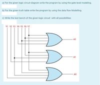
Transcribed Image Text:a) For the given logic circuit diagram write the program by using the gate level modeling.
b) For the given truth table write the program by using the data flow Modelling.
c) Write the test bench of the given logic circuit with all possibilities
Y1 Y2 Y3 Y4 Y5 Y6 Y7
A2
A1
A0
Expert Solution
This question has been solved!
Explore an expertly crafted, step-by-step solution for a thorough understanding of key concepts.
Step by stepSolved in 2 steps with 2 images

Knowledge Booster
Learn more about
Need a deep-dive on the concept behind this application? Look no further. Learn more about this topic, electrical-engineering and related others by exploring similar questions and additional content below.Similar questions
- 5/ Select a suitable example for combinational logic circuit. A) None of the given choices B) Decoders C) Latches D ) PLAarrow_forwardWrite the Boolean expression for the following logic gate circuit, then reduce that expression to its simplest form using any Boolean postulates and theorems. Finally, draw a new gate circuit diagram based on the simplified Boolean expression that performs the exact same logic function.arrow_forwardGive all gates outputarrow_forward
- Describe in a short paragraph the difference between combinational logic circuits and sequential logic circuits.arrow_forwardDesign a combinational circuit using multiplexer for a car chime based on thefollowing system: A car chime or bell will sound if the output of the logic circuit(X) is set to a logic ‘1’. The chime is to be sounded for either of the followingconditions:• if the headlights are left on when the engine is turned off and• if the engine is off and the key is in the ignition when the door is opened.Use the following input names and nomenclature in the design process:• ‘E’ – Engine. ‘1’ if the engine is ON and ‘0’ if the engine is OFF• ‘L’ – Lights. ‘1’ if the lights are ON and ‘0’ if the lights are OFF• ‘K’ – Key. ‘1’ if the key is in the ignition and ‘0’ if the key is not in the ignition• ‘D’ – Door. ‘1’ the door is open and ‘0’ if the door is closed• ‘X’ – Output to Chime. ‘1’ is chime is ON and ‘0’ if chime is OFFarrow_forward(b) Figure Q2(b) shows input waveforms of A, B and C. Draw the logic circuit that will generate the output waveform X. A Inputs B Output X Figure Q2(b) : Input and output waveformsarrow_forward
- Using AND gates OR gates and inverters, draw a schematic for the function F = A&B + A&C + B&C. You do not need to minimize the function.(NEED NEAT HANDWRITTEN SOLUTION ONLY OTHERWISE DOWNVOTE )arrow_forward(a) Find VH and VL for the Schottky DTL gateshown. (b) What are the input currents in thetwo logic states? (c) What is the fanout of the gate?arrow_forwardReduce the Boolean function specified in the truth table below to its minimum SOP form using K-map, where A, B, C are the inputs while X are the outputs. Based on the reduced Boolean function, design the logic circuit using any logic gates. A 0 0 0 0 1 1 1 1 B 0 0 1 1 0 1 с 0 1 0 1 0 1 0 1 X 1 1 0 1 1 1 0 1arrow_forward
- The following diagram shows a logic circuit using a combinatorial chip called A, and a sequential chip called B. Which wiring is legal, the wiring around chip A or the wiring around chip B. Select one: a. the wiring around chip A. b. the wiring around chip B.arrow_forward1. Design a logic circuit with four inputs A,B,C,D as shown in figure1 and one output Y and whose output will be high if only the input is evenly divisible by 3. A B LY D Figure1 I. Find the SOP Boolean expression of the output Y. I. Draw logic circuit using basic gate and verify the result by using any simulation tools. II. Draw a logic circuit by using NAND gate only. |arrow_forward9 Part 1 of 2 Mc Graw Hill Required information Consider the logic gate circuit shown in the given figure. A (S1)-0- B (S2)-0 C (S3)-0- AB B BC B+C What is the Boolean equation for the given figure? ***************** The Boolean equation for the given figure is (Click to select) Note: This is a multi-part question. Once an answer is submitted, you will be unable to return to this part.arrow_forward
arrow_back_ios
SEE MORE QUESTIONS
arrow_forward_ios
Recommended textbooks for you
 Introductory Circuit Analysis (13th Edition)Electrical EngineeringISBN:9780133923605Author:Robert L. BoylestadPublisher:PEARSON
 Delmar's Standard Textbook Of ElectricityElectrical EngineeringISBN:9781337900348Author:Stephen L. HermanPublisher:Cengage Learning
 Programmable Logic ControllersElectrical EngineeringISBN:9780073373843Author:Frank D. PetruzellaPublisher:McGraw-Hill Education
 Fundamentals of Electric CircuitsElectrical EngineeringISBN:9780078028229Author:Charles K Alexander, Matthew SadikuPublisher:McGraw-Hill Education
 Electric Circuits. (11th Edition)Electrical EngineeringISBN:9780134746968Author:James W. Nilsson, Susan RiedelPublisher:PEARSON
 Engineering ElectromagneticsElectrical EngineeringISBN:9780078028151Author:Hayt, William H. (william Hart), Jr, BUCK, John A.Publisher:Mcgraw-hill Education,

Introductory Circuit Analysis (13th Edition)
Electrical Engineering
ISBN:9780133923605
Author:Robert L. Boylestad
Publisher:PEARSON

Delmar's Standard Textbook Of Electricity
Electrical Engineering
ISBN:9781337900348
Author:Stephen L. Herman
Publisher:Cengage Learning

Programmable Logic Controllers
Electrical Engineering
ISBN:9780073373843
Author:Frank D. Petruzella
Publisher:McGraw-Hill Education

Fundamentals of Electric Circuits
Electrical Engineering
ISBN:9780078028229
Author:Charles K Alexander, Matthew Sadiku
Publisher:McGraw-Hill Education

Electric Circuits. (11th Edition)
Electrical Engineering
ISBN:9780134746968
Author:James W. Nilsson, Susan Riedel
Publisher:PEARSON

Engineering Electromagnetics
Electrical Engineering
ISBN:9780078028151
Author:Hayt, William H. (william Hart), Jr, BUCK, John A.
Publisher:Mcgraw-hill Education,