
Elements Of Electromagnetics
7th Edition
ISBN: 9780190698614
Author: Sadiku, Matthew N. O.
Publisher: Oxford University Press
expand_more
expand_more
format_list_bulleted
Related questions
Question
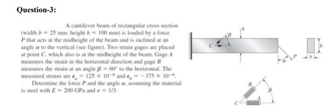

Transcribed Image Text:Question-3:
A cantilever beam of rectangular cross section
(width b= 25 mm. height h 100 mm) is loaded by a force
P that acts at the midheight of the beam and is inclined at an
angle a to the vertical (see figure). Two strain gages are placed
at point C. which also is at the midheight of the beam. Gage A
measures the strain in the horizontal direction and gage B
measures the strain at an angle B= 60 to the horizontal. The
measured strains are e, = 125 x 10-* and e, = -375 x 10-.
Determine the force Pand the angle a, assuming the material
is steel with E= 200 GPa and = 1/3.
Expert Solution
This question has been solved!
Explore an expertly crafted, step-by-step solution for a thorough understanding of key concepts.

This is a popular solution

Trending nowThis is a popular solution!

Step by stepSolved in 4 steps

Knowledge Booster


Learn more about
Need a deep-dive on the concept behind this application? Look no further. Learn more about this topic, mechanical-engineering and related others by exploring similar questions and additional content below.Similar questions
- A 5.1 m long simply supported wood beam carries a uniformly distributed load of 11.3 kN/m, as shown in Figure A. The cross-sectional dimensions of the beam as shown in Figure B are b = 205 mm, d = 460 mm, yH = 77 mm, and yx = 162 mm. Section a-a is located at x = 1.3 m from B. (a) At section a-a, determine the magnitude of the shear stress in the beam at point H. (b) At section a-a, determine the magnitude of the shear stress in the beam at point K. (c) If the allowable shear stress for the wood is 850 kPa, what is the largest distributed load w that can be supported by the beam? х В L Figure Aarrow_forwardThe two bars shown in the figure are used to support a load P. When unloaded, joint B has coordinates (0, 0). After load P is applied, joint B moves to the coordinate position (0.20 in., -0.55 in.). Assume a = 9 ft, b = 6 ft, and h = 7 ft. Determine the normal strain in each bar. B P b harrow_forwardDetermine the normal strain AB and BCarrow_forward
- 4. The simply supported beam has a cross section and a loading as shown in the figure (a) Draw the shear and bending-moment diagrams for the beam (b) Determine the maximum absolute value of the shear force and bending moment. (c) Determine the maximum tensile and compressive stresses in the beam. A 30 kN/m 2 m C 60 kN D 2 m B T 1 150 mm 50 mm Tarrow_forwardDetermine the axial force, shear force, and bending moment at point J located on member AB of the landing gear of an airplane, as shown in the figure.All distances are in inches.arrow_forwardP=50 kN E=200GPa l=1.4 m Ø=16mmarrow_forward
- Athin rectangular polymer plate PQRS of width b = 429 mm and height a = 140 mm is shown in the figure. The plate is deformed so that corner Q is displaced upward by c = 1.6 mm and corner R is displaced leftward by the same amount. Determine the shear strain at corner P after deformation. a Y = y i b Q S a X uradarrow_forwardA surface condenser deals with 12000 kg of steam per hour. Air leakage into the condenser is found to be 4 kg/hr. The vacuum and temperature at the air pump suction are 700 mm of Hg and 36°C respectively. The barometric pressure is 760 mm Hg. Compute the volumetric capacity in m'/min of wet air pump.arrow_forwardA symmetrical framework consisting of threepin-connected bars is loaded by a force P (see figure).The angle between the inclined bars and the horizontalis α = 52°. The axial strain in the middle bar ismeasured as 0.036.Determine the tensile stress in the outer bars ifthey are constructed of a copper alloy having the followingstress-strain relationship:σ = 18,000ε/(1 + 300ε) 0 ≤ ε ≤ 0.03 (σ= ksi)arrow_forward
arrow_back_ios
arrow_forward_ios
Recommended textbooks for you
- Elements Of ElectromagneticsMechanical EngineeringISBN:9780190698614Author:Sadiku, Matthew N. O.Publisher:Oxford University Press
 Mechanics of Materials (10th Edition)Mechanical EngineeringISBN:9780134319650Author:Russell C. HibbelerPublisher:PEARSON
 Thermodynamics: An Engineering ApproachMechanical EngineeringISBN:9781259822674Author:Yunus A. Cengel Dr., Michael A. BolesPublisher:McGraw-Hill Education
  Control Systems EngineeringMechanical EngineeringISBN:9781118170519Author:Norman S. NisePublisher:WILEY
 Mechanics of Materials (MindTap Course List)Mechanical EngineeringISBN:9781337093347Author:Barry J. Goodno, James M. GerePublisher:Cengage Learning
 Engineering Mechanics: StaticsMechanical EngineeringISBN:9781118807330Author:James L. Meriam, L. G. Kraige, J. N. BoltonPublisher:WILEY
Elements Of Electromagnetics
Mechanical Engineering
ISBN:9780190698614
Author:Sadiku, Matthew N. O.
Publisher:Oxford University Press
Mechanics of Materials (10th Edition)
Mechanical Engineering
ISBN:9780134319650
Author:Russell C. Hibbeler
Publisher:PEARSON
Thermodynamics: An Engineering Approach
Mechanical Engineering
ISBN:9781259822674
Author:Yunus A. Cengel Dr., Michael A. Boles
Publisher:McGraw-Hill Education
Control Systems Engineering
Mechanical Engineering
ISBN:9781118170519
Author:Norman S. Nise
Publisher:WILEY
Mechanics of Materials (MindTap Course List)
Mechanical Engineering
ISBN:9781337093347
Author:Barry J. Goodno, James M. Gere
Publisher:Cengage Learning
Engineering Mechanics: Statics
Mechanical Engineering
ISBN:9781118807330
Author:James L. Meriam, L. G. Kraige, J. N. Bolton
Publisher:WILEY