Question

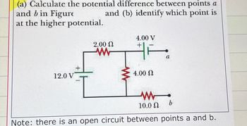
Transcribed Image Text:(a) Calculate the potential difference between points a
and (b) identify which point is
and b in Figure
at the higher potential.
4.00 V
2.00 Ω
+
12.0 V
+
w
ww
4.00 Ω
ww
10.0 Ω
b
a
Note: there is an open circuit between points a and b.
Expert Solution
This question has been solved!
Explore an expertly crafted, step-by-step solution for a thorough understanding of key concepts.
Step by stepSolved in 3 steps with 2 images

Knowledge Booster
Similar questions
- In the figure below, capacitor 1 (C₁ Q₂ C₁ = = (a) Find the final charge on each capacitor after a long time has passed. с C 30.0 μF) initially has a potential difference of 55.0 V and capacitor 2 (C₂ = 5.10 μF) has none. The switches are then closed simultaneously. (b) Calculate the percentage of the initial stored energy that was lost when the switches were closed. %arrow_forwardFor problem 25 part b, calculate the potential at point P in volts using a value of Q2=-3.17 Q1 instead of the value in the stated problem. Answer in 5 sig figs!!arrow_forward(a) Find the equivalent capacitance between points a and b for the group of capacitors connected as shown in the figure above. Take C1 = 2.00 µF, C2 = 14.0 µF, and C3 = 6.00 µF.(b) What charge is stored on C3 if the potential difference between points a and b is 60.0 V?arrow_forward
- The potential in a region between x = 0 and x = 6.00 m is V = a + bx, where a = 15.2 V and b = -3.50 V/m. a) Determine the potential at x= 0, x= 3.00 m, and x= 6.00 m. b) Determine the magnitude (Vm) and direction of the electric field at x= 0, x= 3.00 m, and x= 6.00 m.arrow_forward(a) Find the equivalent capacitance between points a and b for the group of capacitors connected as shown in the figure above. Take C1 = 6.00 µF, C2 = 15.0 µF, and C3 = 6.00 µF.µF(b) What charge is stored on C3 if the potential difference between points a and b is 60.0 V?µCarrow_forwardarrow_forwardc. Charge on C₂ (in nC) = Submit Answer Incorrect. Tries 4/10 Previous Tries d. Voltage across C₂ (in V) = Submit Answer Tries 0/10 e. Charge on C3 (in nC) = Submit Answer Tries 0/10 f. Voltage across C3 (in V) =arrow_forwardUnder typical atmospheric conditions, there is an electric field near the earth’s surface, directed downward, with a magnitude of 100 V/m. If we say that the potential at the earth’s surface is 0 V, what is the potential 1.0 km above the surface?arrow_forwardA simple adjustable parallel-plates capacitor is shown below. The plates have a radius of 8.0 cm and they are separated by a gap of 0.50 cm with nothing in between them. (a) Calculate the capacitance of this capacitor. (b) Calculate the charge stored when a battery of 9 V is connected to the capacitor. (c) Calculate the energy stored in the capacitor. (d) While the battery is still connected to the capacitor, a 0.50 cm-thick piece of wood (dielectric constant ? = 4.0) is inserted into the gap between the plates. Describe and explain what would happen to the capacitor’s voltage, to the capacitance, and to the stored charge.arrow_forwardTwo identical parallel-plate capacitors, each with capacitance 17.0 ?F, are charged to potential difference 48.5 V and then disconnected from the battery. They are then connected to each other in parallel with plates of like sign connected. Finally, the plate separation in one of the capacitors is doubled. (b) Find the potential difference across each capacitor after the plate separation is doubled. (c) Find the total energy of the system after the plate separation is doubled.arrow_forwardIf a proton gains 6x10^-12 J of electrical potential energy as it moves from point A to point B, what is the voltage difference between points A and B, and which point is at the higher potential?arrow_forwardExplain why the work needed to move a charge Q through a potential difference AV is W = QAV, whereas the energy stored in a charged capacitor is U = 1/2 QAV. This answer has not been graded yet. Where does the 1/2 factor come from?arrow_forwardarrow_back_iosSEE MORE QUESTIONSarrow_forward_ios