Structural Analysis
6th Edition
ISBN: 9781337630931
Author: KASSIMALI, Aslam.
Publisher: Cengage,
expand_more
expand_more
format_list_bulleted
Question
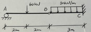
a) Calculate reactions of the beam shown in the figure.
b) Label the reaction on the figure, and draw complete shear and moment diagrams for the beam. Label all transition and maximum values on the diagrams, and indicate regions of positive / negative shear and positive / negative bending.
Please provide any equations, calculations, and explanations.

Transcribed Image Text:A
boke
*
2m
*
B
30kN/m
*
*
2m
3m
Expert Solution
This question has been solved!
Explore an expertly crafted, step-by-step solution for a thorough understanding of key concepts.
Step by stepSolved in 2 steps with 4 images

Knowledge Booster
Similar questions
- For the frame and load shown in the figure,determines the components of all the forces thatthey act on the ABE element.arrow_forwardSolve the shown systems (1-3) using general stiffness method, draw the bending moment diagrams and calculate the reactions. 4 kN/m y A B K 5 m 4 m 45° El: constantarrow_forwardFor the simply supported beam subjected to the loading shown, derive equations for the shear force V and the bending moment M for any location in the beam. (Place the origin at point A.) Let a=1.50 m, b=5.00 m, PA = 75kN, and PC = 90kN. Construct the shear-force and bending-moment diagrams. Calculate the reaction forces By and Dy acting on the beam. Positive values for the reactions are indicated by the directions of the red arrows shown on the free-body diagram below.arrow_forward
- simply supported beam is subjected to a uniform load of 400 lb/ft and a concentrated load of 900 lb as shown in the below figure a. Find the reactions. b. Express the internal shear and moment in terms of x and then draw the shear and moment diagrams for the beam. Label the points of maximum bending on the bending moment diagram. Determine the maximum tensile and compressive stresses due to bending and specify their location. 900 lb =arrow_forwardQ.2) (a) Calculate the support reactions of the loaded beam shown below. (b) Write equations for w(x), V(x) and M(x) of the beam using singularity functions. (c) Sketch the shear-force and bending moment diagrams for the beam for the beam using the Graphical method. Label the values of shear-force and bending-moment at all key points. 350 N.m G 0.5 m4 2m 95 N/m, 200 N 250 N.m 80 N/m 2m 300 N 0.5 marrow_forward
arrow_back_ios
arrow_forward_ios
Recommended textbooks for you

 Structural Analysis (10th Edition)Civil EngineeringISBN:9780134610672Author:Russell C. HibbelerPublisher:PEARSON
 Principles of Foundation Engineering (MindTap Cou...Civil EngineeringISBN:9781337705028Author:Braja M. Das, Nagaratnam SivakuganPublisher:Cengage Learning
 Fundamentals of Structural AnalysisCivil EngineeringISBN:9780073398006Author:Kenneth M. Leet Emeritus, Chia-Ming Uang, Joel LanningPublisher:McGraw-Hill Education
 Traffic and Highway EngineeringCivil EngineeringISBN:9781305156241Author:Garber, Nicholas J.Publisher:Cengage Learning


Structural Analysis (10th Edition)
Civil Engineering
ISBN:9780134610672
Author:Russell C. Hibbeler
Publisher:PEARSON

Principles of Foundation Engineering (MindTap Cou...
Civil Engineering
ISBN:9781337705028
Author:Braja M. Das, Nagaratnam Sivakugan
Publisher:Cengage Learning

Fundamentals of Structural Analysis
Civil Engineering
ISBN:9780073398006
Author:Kenneth M. Leet Emeritus, Chia-Ming Uang, Joel Lanning
Publisher:McGraw-Hill Education


Traffic and Highway Engineering
Civil Engineering
ISBN:9781305156241
Author:Garber, Nicholas J.
Publisher:Cengage Learning