Related questions
Question
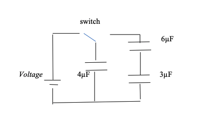
A 12V battery is hooked up to 3 uncharged capacitors. The power supply is turned on only the 4 µF capacitor gets charged. The switch is the moved to the right so the 4µF capacitor will discharge to the 6µF capacitor and the 3µF capacitor until an equilibrium is reached(so it will still have charge and voltage). What is the final charge and voltage on each capacitor?

Transcribed Image Text:Welcome to the Educational Resource on Electrical Circuits!
### Series and Parallel Capacitor Circuit
**Diagram Explanation:**
The illustrated schematic diagram represents an electrical circuit involving capacitors and a switch. Here is a detailed breakdown:
- **Voltage Source:**
- On the left of the diagram, there is a voltage source symbol, denoted by "Voltage." It serves as the power source for the circuit.
- **Switch:**
- Next to the voltage source, we observe a switch. This switch is in the open position, meaning it is currently not allowing electrical flow.
- **Capacitors:**
- The circuit contains three capacitors with the following capacitances:
- **4 µF (microfarads)**
- Connected directly after the switch.
- **6 µF (microfarads)**
- Positioned above the 3 µF capacitor.
- **3 µF (microfarads)**
- Positioned below the 6 µF capacitor and connected in parallel to it.
**Arrangement and Connections:**
- The 4 µF capacitor is connected in series with the switch and the voltage source.
- The 6 µF and 3 µF capacitors are connected in parallel with each other.
- This parallel combination of 6 µF and 3 µF capacitors is then connected in series with the 4 µF capacitor and the switch.
**Functionality:**
- When the switch is closed, the voltage source will begin charging the capacitors.
- The total capacitance of the circuit can be calculated by determining the equivalent capacitance of the 6 µF and 3 µF capacitors in parallel, and then considering the series combination with the 4 µF capacitor.
This arrangement allows for the study of the behavior of series and parallel combinations of capacitors in electrical circuits, demonstrating how total capacitance is affected by different configurations.
Understanding and analyzing such circuits is fundamental in electronics and electrical engineering, and it provides the basis for more complex circuit analysis and design.
Expert Solution
This question has been solved!
Explore an expertly crafted, step-by-step solution for a thorough understanding of key concepts.

This is a popular solution

Trending nowThis is a popular solution!

Step by stepSolved in 5 steps with 8 images

Knowledge Booster

Similar questions
- The circuit in the figure below contains a 90.0 V battery and four capacitors. In the top parallel branch, there are two capacitors, one with a capacitance of C, = 6.00 uf and another with a capacitance of 6.00 uF. In the bottom parallel branch, there are two more capacitors, one with a capacitance of 2.00 uF and another with a capacitance of C, = 8.00 pF. 6.00 uF 2.00 uF 90.0 V (a) What is the equivalent capacitance (in uF) of the entire circuit? (b) What is the charge (in uC) on each capacitor? on C, on C2 on the 6.00 uF capacitor pc on the 2.00 uF capacitor (c) What is the potential difference (in V) across each capacitor? across C, across C, V across the 6.00 µF capacitor across the 2.00 pF capacitorarrow_forwardA leaky capacitor loses 22% of its charge in 13 min. What is the effective time constant of the system? The time constant, t = What fraction of charge (in %) will be on the capacitor after 39 min? Q Qo After what time there will be 4% of the initial charge left on the capacitor? The charge, The time, t = Units Select an answer ✓ x 100% = Units Select an answer ✓ Units Select an answer ✓arrow_forwardA 15 microFarad capacitor is in a circuit with a 4.0 V battery. Electrons will move after the switch is closed. What is the energy stored in the capacitor after the switch is closed long enough time?arrow_forward
- A 243-μF capacitor is connected in series with a 122-μF capacitor. What is the equivalent capacitance of the pair? Express your answer to three significant figures and include appropriate units.arrow_forwardA leaky capacitor loses 5% of its charge in 5 min. What is the effective time constant of the system? The time constant, τ = Units . What fraction of charge (in %) will be on the capacitor after 10 min? The charge, QQ0×100%QQ0×100% = Units . After what time there will be 4% of the initial charge left on the capacitor? The time, t = Units .arrow_forwardA defibrillator containing a 30.2 μF capacitor is used to shock the heart of a patient by holding it to the patient's chest. Just prior to discharging, the capacitor has a voltage of 20.5 kV across its plates. How much energy is released into the patient?arrow_forward
- If it is required to store 32.9 μC of electric charge in a capacitor in an electric circuit, what should the capacitance of the capacitor be if a voltage supply can apply 4.0 V of voltage to the capacitor? Report the number in the unit of μFarrow_forwarda) The network of capacitors shown in the image are all uncharged when a 364V potential is applied between points A and B with the switch S open. How much energy is stored in the network of capacitors? b) The network of capacitors shown in the image are all uncharged when a 185V potential is applied between points A and B with the switch S open. What is the voltage across the lower right 2.0µF capacitor when all of the capacitors are fully charged?arrow_forward
arrow_back_ios
arrow_forward_ios