Steel Design (Activate Learning with these NEW titles from Engineering!)
6th Edition
ISBN: 9781337094740
Author: Segui, William T.
Publisher: Cengage Learning
expand_more
expand_more
format_list_bulleted
Question
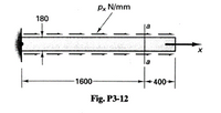
3-12 A 10-mm-thick, low-alloy-steel plate 180 mm wide and 2000 mm long is subjected to a set of uniformly distributed frictional forces along its two edges, as shown in the figure. If the total decrease in the transverse 180-mm dimension at section a--a due to the applied forces is 16 x 10 mm, what is the total elongation of the bar in the longitudinal direction? Let E= 200 GPa and v= 0.25. Assume that the steel behaves as a linearly elastic material.

Transcribed Image Text:Px N/mm
180
1600
-400->
Fig. P3-12
Expert Solution
This question has been solved!
Explore an expertly crafted, step-by-step solution for a thorough understanding of key concepts.
This is a popular solution
Trending nowThis is a popular solution!
Step by stepSolved in 2 steps

Knowledge Booster
Similar questions
- How to solve this question step by steparrow_forwarded-fixed NOTE Do not continue to load the struts after the buckling load has been reached otherwise the struts will become permanently deformed! Enter your results into Table 3. TUAT2 Strut Length Buckling load 1/L2 number (m2) 12,75 918 6,92 (mm) (N) -344 - 275 -195 - 154 - 119 PHE 1 280 330 380 4. 430 OFS 4,34 Table 3 Results for experiment 2 (fixed-fixed) 480 Plot separate graphs of buckling load versus 1/L and calculate the gradient of each line. Establish ratios between each end condition (taking the pinned-pinned condition as 1). Examine the Euler buckling formulae for each end condition and confirm that the experimental and theoretical ratios are similar.arrow_forwardThe thin uniform plate shown has a mass of 100kg and is subjected to a force and couple momentalong its edges. If it is supported in the horizontalplane by a roller at A, a ball-and-socket joint at B,and a cord at C, determine the components ofreaction at these supports to maintain equilibrium. Please provide all written work and show FBD. Thank you!arrow_forward
- Q.2 Three bars each made of different materials are Steel Copper Ecu- 120 GPa ag = 12(10-)/C a = 21(10-")/"C a = 17(10-)C Acu = 515 mm? Brass connected together and placed between two E= 200 GPa E= 100 GPa walls when the temperature is T1 = 12°C. %3D Detemine the force exerted on the rigid A = 200 mm? Ape- 450 mm supports when the temperature becomes T2 %3D 18°C. The material properties and cross- 300 mm 200 mm 100 mm sectional area of each bar are given in the figure. (Marks = 10, CLO 3)arrow_forwardIADC classification (4-1-4-T) refers to what kind of a bit? IADC classification (D-7-1- 4) refers to what kind of a bit?arrow_forwardThe bar has a constant cross section.....arrow_forward
- Photos 4 Crop & rotate Filters * Adjustments 2 Undo all Redo all Crop & rotate Straightening 0 ° Two round bars are joined and used as a tension member as illustrated. The modulus of elasticity is 200 GPa for steel and 70 GPa for aluminum. Rotate D4 Flip O Aspect ratio : Custom Aluminum 100 mm diameter Reset bar 50 mm diaineter P Steel bar +280 mm 400 mm Determine the magnitude of the force P (in kN) that willI lengthen the two bars 0.45 mm. * Your answer Save a copy Cancel 6:50 PM O Type here to search 日 28°C Partly cloudy 4)) ENG 23/09/2021arrow_forward1.8-4 Lateral bracing for an elevated pedestrian walkway is shown in the figure part (a). The thickness of the clevis plate 1. = 16 mm and the thickness of the gusset plate t = 20 mm [see figure part (b)]. The maximum force in the diagonal bracing is expected to be F = 190 kN. If the allowable shear stress in the pin is 90 MPa and the allowable bearing stress between the pin and both the clevis and gusset plates is 150 MPa, what is the minimum required diameter dmin of the pin? Pin Diagonal brace (a) (© Barry Goodno)arrow_forwardJU 4.7 and 4.8 Two W4 × 13 rolled sections are welded together as shown. Knowing that for the steel alloy used, øy = 36 ksi and ơŋ 58 ksi and using a factor of safety of 3.0, determine the largest couple that can be applied when the assembly is bent about the z axis. 14 Fig. P4.7 Fig. P4.8 V Carrow_forward
- O 88 130% v - + I Annotate T| Edit Trial expired Unlock Full Version ENGR 263 + A A A T O 4.10 Member AB is the beam under consideration. As shown in the illustration of the loading condition, member AB is an overhanging beam that supports a uniformly distributed roof load of 500 lb/ft. It also carries concentrated loads from a rooftop HVAC unit (4000 lb), an interior hanging display support (2000 lb), and a marquee sign (3000 lb). Marquee overnang Displau SLIPPort II Raof Kiots Ol I W = 500 Ib/Ft A B 4000 b 2000 000 I Steel beam !! I1 3 FE 5 FE - Ft RoOFtop HVAC unit 10 FE 4 Ft Marquee sign< R R2 Steel beam (negligible weight) Free-body diagram Dispiay Support Loading conditionarrow_forwardMex Force 15 KN APPlied on nail what is The Max V If spacing between Nail is 75cm 2 15cm 5cm 15cm en 10cm 5cm 9cmarrow_forwardComplete Table P4.2. For a member where a deflection criterion controls, which material would require a larger cross section? What about for a member where tension controls? TABLE P4.2 Mild Steel 7178 T76 Aluminum Yield Strength Ultimate Strength Modulus of Elasticityarrow_forward
arrow_back_ios
SEE MORE QUESTIONS
arrow_forward_ios
Recommended textbooks for you
 Steel Design (Activate Learning with these NEW ti...Civil EngineeringISBN:9781337094740Author:Segui, William T.Publisher:Cengage Learning

Steel Design (Activate Learning with these NEW ti...
Civil Engineering
ISBN:9781337094740
Author:Segui, William T.
Publisher:Cengage Learning