
Elements Of Electromagnetics
7th Edition
ISBN: 9780190698614
Author: Sadiku, Matthew N. O.
Publisher: Oxford University Press
expand_more
expand_more
format_list_bulleted
Related questions
Concept explainers
Question
The pedal crank for a bicycle has the cross section shown. If it is fixed to the gear at B and does not rotate while subjected to a force of 75 lb, determine the principal stresses on the cross section at point C.
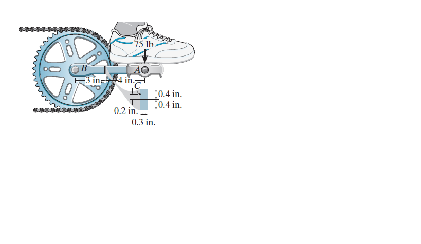

Transcribed Image Text:75 lb
AO
3 in-4 in.
T0.4 in.
[0.4 in.
0.2 in.
0.3 in.
Expert Solution
This question has been solved!
Explore an expertly crafted, step-by-step solution for a thorough understanding of key concepts.

This is a popular solution

Trending nowThis is a popular solution!

Step by stepSolved in 5 steps with 13 images

Knowledge Booster


Learn more about
Need a deep-dive on the concept behind this application? Look no further. Learn more about this topic, mechanical-engineering and related others by exploring similar questions and additional content below.Similar questions
- The propeller shaft of the tugboat is subjected to the compressive force and torque shown. If the shaft has an inner diameter of 100 mm and an outer diameter of 150 mm, determine the principal stresses at a point A located on the outer surface.arrow_forwardThe following shaft consists of a tube AB and a solid rod BC. The tube has an inner diameter of 25 mm and an outer diameter of 30 mm. The rod has a diameter of 15 mm. Determine the average normal stress at point D. The average normal stress at point D isarrow_forwardQI/ The supporting wheel on a scaffold is held in place on the leg using a 5-mm- diameter pin as shown. If the wheel is subjected to a normal force of 5 kN, determine the average shear stress developed in the pin. Neglect friction between the inner scaffold puller leg and the tube used on the wheel. 5 kNarrow_forward
- The wide-flange beam is subjected to the 50-kN force. Determine the principal stresses in the beam at point A located on the web at the bottom of the upper flange. Although it is not very accurate, use the shear formula to calculate the shear stress. A B₂ ➜ 10 mm- B 200 mm 12 mm 250 mm 12 mm -3 m 50 kNarrow_forwardThe wheel on a trolley is held in place on the leg using a 5-mm-radius pin. If the wheel is subjected to a normal force of 10 kN, determine the average shear stress in the pin. Neglect the friction force and assume the pin only supports the vertical 10-kN loadarrow_forwardThe solid cylinder having a radius r is placed in a sealed container and subjected to a pressure p. Determine the stress components acting at point A located on the center line of the cylinder. Draw Mohr's circles for the element at this point. Aarrow_forward
- The solid bar has a diameter of 50 mm. The two forces and the torque Tx are acting at the origin of the x-y-z coordinate system which is coincident with the centroid of the cross-section of the bar; the 1800 N force is acting in the y-z plane and torque Tx is acting about the x-axis. Determine the state of stress at points A and B, and show the respective stress components acting on differential elements located at these two points. 200 mm/ y 200 mm 1200 N Tx = 40 N.m %3D 1800 Narrow_forwardSolve shoe all steps and solitionarrow_forwardDetermine state of stress at the remaining points (P2, P3 and P4). Calculate the maximumprincipal (σ1) and maximum in-plane stress (τmax) for the remaining points (P2, P3 and P4) located at Point A.arrow_forward
- Q2) The shaft is supported by a smooth thrust bearing at A and a smooth journal bearing at B. If the shaft is made from a material having an allowable shear stress of t = 65 MPa, determine allow the maximum value for the force P. D 1 m -2 m- 1 m P 25 mm 40 mmarrow_forwardThe 3/4-in.-diameter shaft is subjected to the loading shown. Determine the stress components at point A. Sketch the results on a volume element located at this point. The journal bearing at C can exert only force components Cyand Cz on the shaft, and the thrust bearing at D can exert force components Dx, Dy, and Dz on the shaft.arrow_forwardDetermine the maximum ram force P that can be applied to the clamp at D if the allowable normal stress for the material is sallow = 180 MPa.arrow_forward
arrow_back_ios
SEE MORE QUESTIONS
arrow_forward_ios
Recommended textbooks for you
- Elements Of ElectromagneticsMechanical EngineeringISBN:9780190698614Author:Sadiku, Matthew N. O.Publisher:Oxford University Press
 Mechanics of Materials (10th Edition)Mechanical EngineeringISBN:9780134319650Author:Russell C. HibbelerPublisher:PEARSON
 Thermodynamics: An Engineering ApproachMechanical EngineeringISBN:9781259822674Author:Yunus A. Cengel Dr., Michael A. BolesPublisher:McGraw-Hill Education
  Control Systems EngineeringMechanical EngineeringISBN:9781118170519Author:Norman S. NisePublisher:WILEY
 Mechanics of Materials (MindTap Course List)Mechanical EngineeringISBN:9781337093347Author:Barry J. Goodno, James M. GerePublisher:Cengage Learning
 Engineering Mechanics: StaticsMechanical EngineeringISBN:9781118807330Author:James L. Meriam, L. G. Kraige, J. N. BoltonPublisher:WILEY
Elements Of Electromagnetics
Mechanical Engineering
ISBN:9780190698614
Author:Sadiku, Matthew N. O.
Publisher:Oxford University Press
Mechanics of Materials (10th Edition)
Mechanical Engineering
ISBN:9780134319650
Author:Russell C. Hibbeler
Publisher:PEARSON
Thermodynamics: An Engineering Approach
Mechanical Engineering
ISBN:9781259822674
Author:Yunus A. Cengel Dr., Michael A. Boles
Publisher:McGraw-Hill Education
Control Systems Engineering
Mechanical Engineering
ISBN:9781118170519
Author:Norman S. Nise
Publisher:WILEY
Mechanics of Materials (MindTap Course List)
Mechanical Engineering
ISBN:9781337093347
Author:Barry J. Goodno, James M. Gere
Publisher:Cengage Learning
Engineering Mechanics: Statics
Mechanical Engineering
ISBN:9781118807330
Author:James L. Meriam, L. G. Kraige, J. N. Bolton
Publisher:WILEY