Introductory Circuit Analysis (13th Edition)
13th Edition
ISBN: 9780133923605
Author: Robert L. Boylestad
Publisher: PEARSON
expand_more
expand_more
format_list_bulleted
Question

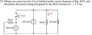
Transcribed Image Text:53. Obtain an expression for i(t) as labeled in the circuit diagram of Fig. 8.84, and
determine the power being dissipated in the 40 2 resistor at t = 2.5 ms.
t=0
i(t)
30 Ω
w
200 mA 4002
30 m
100 mA(
Expert Solution
This question has been solved!
Explore an expertly crafted, step-by-step solution for a thorough understanding of key concepts.
Step by stepSolved in 2 steps with 3 images

Knowledge Booster
Similar questions
- Hi im struggling to understand how you would sketch DC component Va and AC component va for the following questions. Could you show me how on both questions so i understand how to do it on different scenarios. thank you.Also is there like a universal formula i can use as every graph is not the same. Also can u show how to identify the period of each graph.arrow_forwardQuestion 8. 12V in R₁ A R₁ 5 V C R₂2 w R₂ 4 Consider the circuit below, where the capacitor is uncharged, and the switch is open. The different elements of the circuit have the following values: R₁ = 22, R₂ = 22, R3 = 422, R₁ = 82, R₁ = 82 and C = 10 µF. What is the current I₁ in the circuit when the switch is moved to position 1? Enter your answer, in Amps, in the box below. The answer is acceptable within a tolerance of 0.1 A. h₁: R3 After a long time that the switch has been closed, what is the voltage Vc across the capacitor? Enter your answer, in Volts, in the box below. The answer is acceptable within a tolerance of 0.1 V. Vc:arrow_forwardYou are investigating the electrical testing circuits and find that, in an inductive circuit, the relationship between instantaneous current i (amps) and the time t (secs) is given by: i = 12.5(1-e-t/CR) You have been asked to determine the time taken for the current to rise from 1 to 2 amps given your own R and C values as follows. R= 140 C= 90arrow_forward
- Electronic 2arrow_forward8a. R1 2k0 Hilt Use the differential equation approach to find v (t) for t> 0 in the circuit in Figure 8. Show all V1 10V R2 www 4k0 R5 ww 3k0 switch closes at 1-0 R3 1k0 C1 HH 100μF V2 5V a R4 34k0 vo(t)arrow_forwardChange the question format or circle and draw the circle so that it is a difficult idea and solve the question with a pen and paperarrow_forward
- For the circuit in Figure 3 the switch is in the left position for several minutes: (a) Find the Initlal voltage, V, on the capacitor just before the switch is flipped (b) Find an expression v(t) that describes the voltage across the 20 N resistor after the switch has been Figure 3 U 09 flipped to the right NOTE: Remember what we said in class: use a Circuit-Specific Equation to get a value you know. Then solve for whatever else the problem asks for +50 µF 380 0 20 2arrow_forward8.3.3 For the RLC circuit shown in the image below, if R1 = 7 2 and R2 = 7 2, C = 0.36 F, and the power source Vs = 18 V, determine the initial value VR (0T). %3D Please pay attention: the numbers may change since they are randomized. Your answer must include 2 places after the decimal point, and proper SI unit. R2 Vc + VR R1 2u(t) A Vs Your Answer: Answer units 118 llarrow_forward8. The switches in the circuit shown below change position at time t = 0. Find vo(t) for t ≥ 0.arrow_forward
- Switches 1 and 2 in the circuit are synchronized. When switch 1 is opened, switch 2 closes and viceversa. Switch 1 has been open a long time before closing at t=0. FindiL(t) for t≥0.arrow_forward100 Ω 100 µF 20 Ω 800 mH Use the concept of current division to find the steady-state expression for i.(t) in the circuit in if ig(t) = 60cos 250t mAarrow_forwardIn the following circuit, use either differential equation approach or the shortcut method to find io(t) fort 0. State which method you are using. 62" kV 12 o (t) t 0arrow_forward
arrow_back_ios
SEE MORE QUESTIONS
arrow_forward_ios
Recommended textbooks for you
 Introductory Circuit Analysis (13th Edition)Electrical EngineeringISBN:9780133923605Author:Robert L. BoylestadPublisher:PEARSON
 Delmar's Standard Textbook Of ElectricityElectrical EngineeringISBN:9781337900348Author:Stephen L. HermanPublisher:Cengage Learning
 Programmable Logic ControllersElectrical EngineeringISBN:9780073373843Author:Frank D. PetruzellaPublisher:McGraw-Hill Education
 Fundamentals of Electric CircuitsElectrical EngineeringISBN:9780078028229Author:Charles K Alexander, Matthew SadikuPublisher:McGraw-Hill Education
 Electric Circuits. (11th Edition)Electrical EngineeringISBN:9780134746968Author:James W. Nilsson, Susan RiedelPublisher:PEARSON
 Engineering ElectromagneticsElectrical EngineeringISBN:9780078028151Author:Hayt, William H. (william Hart), Jr, BUCK, John A.Publisher:Mcgraw-hill Education,

Introductory Circuit Analysis (13th Edition)
Electrical Engineering
ISBN:9780133923605
Author:Robert L. Boylestad
Publisher:PEARSON

Delmar's Standard Textbook Of Electricity
Electrical Engineering
ISBN:9781337900348
Author:Stephen L. Herman
Publisher:Cengage Learning

Programmable Logic Controllers
Electrical Engineering
ISBN:9780073373843
Author:Frank D. Petruzella
Publisher:McGraw-Hill Education

Fundamentals of Electric Circuits
Electrical Engineering
ISBN:9780078028229
Author:Charles K Alexander, Matthew Sadiku
Publisher:McGraw-Hill Education

Electric Circuits. (11th Edition)
Electrical Engineering
ISBN:9780134746968
Author:James W. Nilsson, Susan Riedel
Publisher:PEARSON

Engineering Electromagnetics
Electrical Engineering
ISBN:9780078028151
Author:Hayt, William H. (william Hart), Jr, BUCK, John A.
Publisher:Mcgraw-hill Education,