Elements Of Electromagnetics
7th Edition
ISBN: 9780190698614
Author: Sadiku, Matthew N. O.
Publisher: Oxford University Press
expand_more
expand_more
format_list_bulleted
Concept explainers
Question
thumb_up100%
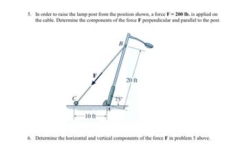
Can someone please help me to solve question 6? Please show all work, formulas, and diagrams. Please and thank you!!!

Transcribed Image Text:5. In order to raise the lamp post from the position shown, a force F= 200 lb. is applied on
the cable. Determine the components of the force F perpendicular and parallel to the post.
B
A
20 ft
75°
A
10 ft-
6. Determine the horizontal and vertical components of the force F in problem 5 above.
Expert Solution
arrow_forward
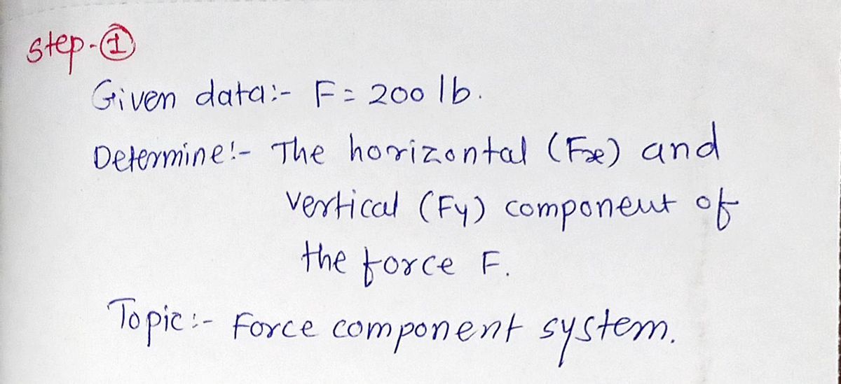
Step 1

Step by stepSolved in 2 steps with 3 images

Knowledge Booster
Learn more about
Need a deep-dive on the concept behind this application? Look no further. Learn more about this topic, mechanical-engineering and related others by exploring similar questions and additional content below.Similar questions
- Find the forces in the three members of the space truss shown in the figure. 600 mm 500 mm 820 mm- 550 mm 625 mm 950 Narrow_forwardGiven the magnitudes of the applied forces on the truss shown below are 0 = 2 kN, P = 3 kN, Q = 3 kN, R = 5 kN, S = 3 kN, T= 4 kN and U = 4 kN. kN P kN kN R kN S kN T kN KN H. 0.4 m K A 0.8 m 0.8 m 0.8 m 0.8 m 0.8 m 0.8 m Determine the forces in members EF, CF and EG. Answers (tolerance 0.5 kN, observe tension positive sign convention): FEF =数字 单位 FCF =数字 单位 FEG = 单位 B.arrow_forward6.62 Neglect the mass of the pulleys and the link. The block has a weight of 230 lb and the cord is attached to the pin at B. The pulleys have radii of r1 = 2 in. and r2 = 1 in. Determine the force P on the cord. Determine the angle θ that the pulley-supporting link AB makes with the vertical.arrow_forward
- The jaws and bolts of the wood clamp in Fig- are parallel. The bolts pass through swivel mounts so that no moments act on them. The clamp exerts forces of 300 N on each side of the board. Treat the forces on the boards as uniformly distributed over the contact areas and determine the forces in each of the bolts. Show on a sketch all forces acting on the upper jaw of the clamp. D 100 mm 150 mm B H00 mm75 mm-100 mm-arrow_forward1: When a force of 2 lb is applied to the handles of the brad squeezer, it pulls in the smooth rod AB. Determine the force P exerted on each of the smooth brads at C and D. (Note that P is not an external force applied to this system, it is shown in the figure to show you where force P is acting within the system (between the thin rods and the wood block.) 2 lb 0.25 in. -2 in- P E 1.5 in. 1 in.f 1.5 in. B D - 2 in.- 2 lbarrow_forwardThe system shown consists of three cables; 1, 2 and 3. Cable 1 passes through a frictionless pulley. A 6 kg mass is suspended. Determine the force in cable 3 considering the following data: y1 = 1.3 m, y2 = 1.1 m, y3 = 1.8 m, and x1 = 2.7 m.arrow_forward
- 4. Not a graded question.arrow_forward(Please, show all process. ) Use the method of MEMBERS to determine the true magnitude and direction of the forces in members1 and 2 of the frame shown below in Fig 3.4.arrow_forward30 cm 18 cm Hom Scm Hom Sum 2. The 30 cm handle is connected rigidly to the 5cm bar at a right angle. Determine the force developed at A if a force P = 100 N is applied perpendicular to the handle when the handle is at the position indicated.arrow_forward
- The force P on the handle of the positioning lever produces a vertical compression of 56lb in the coiled spring in the position shown. Determine the magnitude of the corresponding force exerted by the pin at O on the lever. Assume a = 3.4in. b = 8.6in.arrow_forwardChapter 3, Problem 3/073 The 46-lb rectangular access door is held in the 90° open position by the single prop CD. Determine the force F in the prop and the magnitude of the force normal to the hinge axis AB in each of the small hinges A and B. B 14" 48" 42" 30" Answers: F = Ib A = Ib В - Ib Click if you would like to Show Work for this question: Open Show Workarrow_forward4/2 Determine the force in each member of the loaded truss. Discuss the effects of varying the angle of the 45 support surface at C.arrow_forward
arrow_back_ios
SEE MORE QUESTIONS
arrow_forward_ios
Recommended textbooks for you
 Elements Of ElectromagneticsMechanical EngineeringISBN:9780190698614Author:Sadiku, Matthew N. O.Publisher:Oxford University Press
 Mechanics of Materials (10th Edition)Mechanical EngineeringISBN:9780134319650Author:Russell C. HibbelerPublisher:PEARSON
 Thermodynamics: An Engineering ApproachMechanical EngineeringISBN:9781259822674Author:Yunus A. Cengel Dr., Michael A. BolesPublisher:McGraw-Hill Education
 Control Systems EngineeringMechanical EngineeringISBN:9781118170519Author:Norman S. NisePublisher:WILEY
 Mechanics of Materials (MindTap Course List)Mechanical EngineeringISBN:9781337093347Author:Barry J. Goodno, James M. GerePublisher:Cengage Learning
 Engineering Mechanics: StaticsMechanical EngineeringISBN:9781118807330Author:James L. Meriam, L. G. Kraige, J. N. BoltonPublisher:WILEY

Elements Of Electromagnetics
Mechanical Engineering
ISBN:9780190698614
Author:Sadiku, Matthew N. O.
Publisher:Oxford University Press

Mechanics of Materials (10th Edition)
Mechanical Engineering
ISBN:9780134319650
Author:Russell C. Hibbeler
Publisher:PEARSON

Thermodynamics: An Engineering Approach
Mechanical Engineering
ISBN:9781259822674
Author:Yunus A. Cengel Dr., Michael A. Boles
Publisher:McGraw-Hill Education

Control Systems Engineering
Mechanical Engineering
ISBN:9781118170519
Author:Norman S. Nise
Publisher:WILEY

Mechanics of Materials (MindTap Course List)
Mechanical Engineering
ISBN:9781337093347
Author:Barry J. Goodno, James M. Gere
Publisher:Cengage Learning

Engineering Mechanics: Statics
Mechanical Engineering
ISBN:9781118807330
Author:James L. Meriam, L. G. Kraige, J. N. Bolton
Publisher:WILEY