Structural Analysis
6th Edition
ISBN: 9781337630931
Author: KASSIMALI, Aslam.
Publisher: Cengage,
expand_more
expand_more
format_list_bulleted
Question
thumb_up100%
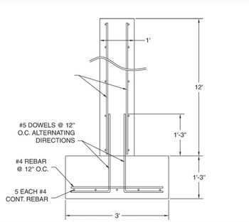
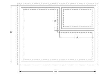
Determine the amount of rebar needed for the foundation walls shown in the figures. Allow for two inches of cover. Add 10 percent for lap and waste to the continuous bars. Horizontal and vertical rebars should be "#4 Rebar @ 12" O.C Bothways".

Transcribed Image Text:The diagram illustrates a portion of a reinforced concrete structure with specifications for dowels and rebar placement.
- **Structure Dimensions**: The total height of the structure is 12 feet. The bottom section, resembling a base, is 3 feet wide and 1 foot 3 inches tall, located at the base of the structure.
- **Rebar Details**:
- The base contains 5 pieces of continuous #4 reinforcing bars (rebar).
- Additional #4 rebar is placed at 12-inch on-center (O.C.) spacing.
- **Dowels Specifications**:
- #5 dowels are placed at 12-inch O.C., alternating directions, along the vertical section of the structure.
- These dowels extend from the base into the vertical element, which also rises 12 feet high, spaced 1 foot apart horizontally.
This setup describes a typical reinforcement plan for vertical and horizontal elements in a concrete structure, illustrating how reinforcements are integrated to provide structural stability and integrity.

Transcribed Image Text:The image depicts a floor plan with dimensions provided.
- The overall outer rectangle measures 40 feet in width and 30 feet in height.
- Inside this larger rectangle, there is a smaller rectangular section located in the upper right corner.
- This smaller rectangle has its bottom edge positioned 18 feet from the left side of the larger rectangle.
- Additionally, the left edge of the smaller rectangle is positioned 12 feet from the top of the larger rectangle.
The floor plan consists of dashed lines indicating the boundaries of both the larger and smaller rectangles, providing a clear visual representation of their placement and dimensions within the space.
Expert Solution
This question has been solved!
Explore an expertly crafted, step-by-step solution for a thorough understanding of key concepts.
This is a popular solution
Trending nowThis is a popular solution!
Step by stepSolved in 2 steps

Knowledge Booster
Learn more about
Need a deep-dive on the concept behind this application? Look no further. Learn more about this topic, civil-engineering and related others by exploring similar questions and additional content below.Similar questions
- Help with this problem pleasearrow_forwardDetermine the maximum aggregate size (MAS) for an 18" wide foundation wall that has two layers of rebars. It is comprised of number 4 rebar at 6" on center in the horizontal direction and number 6 rebar spaced at 2" on center in the vertical direction. It has 1.5" clear cover on the side of the wallarrow_forwardPlease show all intermediate steps such as free body diagram, equations used, problem setup, and etc so that your approach can be easily followedarrow_forward
arrow_back_ios
arrow_forward_ios
Recommended textbooks for you

 Structural Analysis (10th Edition)Civil EngineeringISBN:9780134610672Author:Russell C. HibbelerPublisher:PEARSON
 Principles of Foundation Engineering (MindTap Cou...Civil EngineeringISBN:9781337705028Author:Braja M. Das, Nagaratnam SivakuganPublisher:Cengage Learning
 Fundamentals of Structural AnalysisCivil EngineeringISBN:9780073398006Author:Kenneth M. Leet Emeritus, Chia-Ming Uang, Joel LanningPublisher:McGraw-Hill Education
 Traffic and Highway EngineeringCivil EngineeringISBN:9781305156241Author:Garber, Nicholas J.Publisher:Cengage Learning


Structural Analysis (10th Edition)
Civil Engineering
ISBN:9780134610672
Author:Russell C. Hibbeler
Publisher:PEARSON

Principles of Foundation Engineering (MindTap Cou...
Civil Engineering
ISBN:9781337705028
Author:Braja M. Das, Nagaratnam Sivakugan
Publisher:Cengage Learning

Fundamentals of Structural Analysis
Civil Engineering
ISBN:9780073398006
Author:Kenneth M. Leet Emeritus, Chia-Ming Uang, Joel Lanning
Publisher:McGraw-Hill Education


Traffic and Highway Engineering
Civil Engineering
ISBN:9781305156241
Author:Garber, Nicholas J.
Publisher:Cengage Learning