Introductory Circuit Analysis (13th Edition)
13th Edition
ISBN: 9780133923605
Author: Robert L. Boylestad
Publisher: PEARSON
expand_more
expand_more
format_list_bulleted
Concept explainers
Question

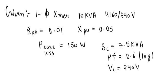
Transcribed Image Text:4.27 A 10-KVA, 4160/240-V, single-phase transformer has a per-unit resistance of
0.01 and a per-unit reactance of 0.05. It has a core loss at rated voltage of 150 W.
The transformer supplies 7.5 KVA at 240 V and 0.6 power factor lagging to a load
connected to its secondary terminals.
a. Determine the equivalent impedance in ohms referred to the primary side.
b. Find the input voltage.
c. Determine the efficiency of the transformer.
Expert Solution
arrow_forward
Step 1

Step by stepSolved in 3 steps with 3 images

Knowledge Booster
Learn more about
Need a deep-dive on the concept behind this application? Look no further. Learn more about this topic, electrical-engineering and related others by exploring similar questions and additional content below.Similar questions
- Find the following : 1.Ripple Voltage (vpp) 2. Zero-to peak ripple(Vop) 3.secondary winding of the transformer high line and low linearrow_forwardConsider the three single-phase two-winding transformers shown in Figure. 3. The high-voltage windings are connected in Y. (a) For the low-voltage side, connect the windings in A, and label the terminals a, b, and c in accordance with the American standard. (b) Relabel the terminals a', b', and c' such that VAN is 90° out of phase with V₂'b' for positive sequence. DI H₂ Figure. 3: Three-Winding Transformerarrow_forwardConstruct the circuit in Figure 1 in the Circuit JS simulator. Note that the voltage source is given in RMS. Within Circuit JS while defining the max voltage of the voltage source include “rms” after the number to tell Circuit JS that this is a rms value. Also note that there are additional parameters when instantiating a transformer in Circuit JS. Leave these at the default values. Additionally, transformers may have problems simulating in Circuit JS. Answer the following: 1. From the simulation results, determine the power dissipated in R2 and compare to the expected value from the previous section.2. Change the transformer ratio (“Ratio” as a fraction when you “Edit…” the transformer component) to the value calculated in the previous section to provide maximum power transfer in R2. Note: In Circuit JS, Transformer Ratio = Primary/Secondary.3. Rerun the simulation, calculate the power dissipated in R2 and compare to the expected value from the previous section.4. Change the…arrow_forward
- 2. Given three identical ideal single-phase transformers with each rated at 100KVA and 7kV/3.5kV, they are connected as a three-phase transformer bank. The three-phase transformer has high voltage side connected in delta and the low voltage side is connected in wye. A three-phase 200KVA, wye connected load is connected at the low voltage side of the transformer. Calculate the following: a. Rated line-to-line voltage on each side b. Line current on each side of the transformerarrow_forwarda single-phase transformer serves a 7.2kw resistive loadlocated 200 ft from the transformer. each conductor from the transformer to load has an impedence of (0.78+j0.052) ohms per 1000ft. if the voltage at the load terminal is 240v, the magnitude of the voltage (v) at the transformer secondary is most nearly:arrow_forwardDefine all the losses in the transformer with the diagram and then define the hysterisis loss with thw graph.arrow_forward
- Vr 3. For a 1.2 accuracy class potential transformer used at a lagging phase angle y of 10', the RCF value is A. 0.991. B. 0.988. C. 0.977. D. 0.999. primary connection scheme that must be used witharrow_forwardThe equivalent resistance and reactance referred to the secondary side of a 10 kVA, 2200/440 V, single phase transformer are 0.3 and 1.20 respectively. Then find the full load voltage regulation at (i) 0.8 lagging (ii) unity and (iii) 0.6 leading power factor.arrow_forward
arrow_back_ios
arrow_forward_ios
Recommended textbooks for you
 Introductory Circuit Analysis (13th Edition)Electrical EngineeringISBN:9780133923605Author:Robert L. BoylestadPublisher:PEARSON
 Delmar's Standard Textbook Of ElectricityElectrical EngineeringISBN:9781337900348Author:Stephen L. HermanPublisher:Cengage Learning
 Programmable Logic ControllersElectrical EngineeringISBN:9780073373843Author:Frank D. PetruzellaPublisher:McGraw-Hill Education
 Fundamentals of Electric CircuitsElectrical EngineeringISBN:9780078028229Author:Charles K Alexander, Matthew SadikuPublisher:McGraw-Hill Education
 Electric Circuits. (11th Edition)Electrical EngineeringISBN:9780134746968Author:James W. Nilsson, Susan RiedelPublisher:PEARSON
 Engineering ElectromagneticsElectrical EngineeringISBN:9780078028151Author:Hayt, William H. (william Hart), Jr, BUCK, John A.Publisher:Mcgraw-hill Education,

Introductory Circuit Analysis (13th Edition)
Electrical Engineering
ISBN:9780133923605
Author:Robert L. Boylestad
Publisher:PEARSON

Delmar's Standard Textbook Of Electricity
Electrical Engineering
ISBN:9781337900348
Author:Stephen L. Herman
Publisher:Cengage Learning

Programmable Logic Controllers
Electrical Engineering
ISBN:9780073373843
Author:Frank D. Petruzella
Publisher:McGraw-Hill Education

Fundamentals of Electric Circuits
Electrical Engineering
ISBN:9780078028229
Author:Charles K Alexander, Matthew Sadiku
Publisher:McGraw-Hill Education

Electric Circuits. (11th Edition)
Electrical Engineering
ISBN:9780134746968
Author:James W. Nilsson, Susan Riedel
Publisher:PEARSON

Engineering Electromagnetics
Electrical Engineering
ISBN:9780078028151
Author:Hayt, William H. (william Hart), Jr, BUCK, John A.
Publisher:Mcgraw-hill Education,