
Introduction to Chemical Engineering Thermodynamics
8th Edition
ISBN: 9781259696527
Author: J.M. Smith Termodinamica en ingenieria quimica, Hendrick C Van Ness, Michael Abbott, Mark Swihart
Publisher: McGraw-Hill Education
expand_more
expand_more
format_list_bulleted
Question
thumb_up100%
i have calculate friction and reynolds but dont know how to calc the guage pressure needed
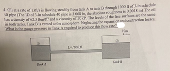
Transcribed Image Text:**Transcription and Explanation for Educational Website**
---
**Problem Statement:**
4. Oil at a rate of 13 ft/s is flowing steadily from tank A to tank B through 1000 ft of 3-in schedule 40 pipe (The ID of 3-in schedule 40 pipe is 3.068 in, the absolute roughness is 0.0018 in). The oil has a density of 62.3 lbm/ft³ and a viscosity of 50 cP. The levels of the free surfaces are the same in both tanks. Tank B is vented to the atmosphere. Neglecting the expansion and contraction losses, what is the gauge pressure in Tank A required to produce this flow rate?
**Diagram Explanation:**
- **Tanks and Flow:**
- There are two tanks, labeled as Tank A and Tank B.
- Oil flows from Tank A to Tank B through a horizontal pipeline.
- **Pipeline Details:**
- The pipeline is 1000 ft in length.
- It is a 3-inch schedule 40 pipe, with an inner diameter (ID) of 3.068 inches and an absolute roughness of 0.0018 inches.
- **Flow Characteristics:**
- The flow rate of oil is 13 ft/s.
- Tank B is vented to the atmosphere, indicating atmospheric pressure in Tank B.
- **Physical Properties:**
- The oil has a density of 62.3 lbm/ft³.
- The oil viscosity is given as 50 centipoise (cP).
The task is to determine the gauge pressure in Tank A needed to achieve the specified flow rate, considering that Tank B is at atmospheric pressure and ignoring expansion and contraction losses.
![**Transcription for Educational Website**
This image contains two equations used in fluid mechanics for calculating the friction factor and Reynolds number in a pipe system.
1. **Friction Factor Equation:**
\[
f = 0.00135 \left[ 1 + \left( 20,000 \cdot \left( \frac{\epsilon}{D} + \frac{10^6}{R} \right) \right)^{\frac{1}{3}} \right]
\]
Breaking it down:
- \( f = 0.00135 \left[ 1 + \left( 20,000 \cdot \left( \frac{0.0018 \, \text{in}}{3.068 \, \text{in}} \right) + \frac{10^6}{6162.63} \right) \right] \)
- The result of the calculation is \( f = 0.000888 \).
2. **Reynolds Number Equation:**
\[
R_e = \frac{\rho DV}{\mu}
\]
Components in this equation:
- The variables are replaced by given values:
\[
R_e = \left( 3.068 \, \text{in} \times \frac{1 \, \text{ft}}{12 \, \text{in}} \right) (13 \, \text{ft/s}) \left( 62.3 \, \frac{\text{lbm}}{\text{ft}^3} \right)
\]
- The denominator is:
\[
50 \, \text{cP} \times 6.72 \times 10^{-4} \, \frac{\text{lbm}}{\text{ft.s}}
\]
- The calculated result is \( R_e = 6162.63 \).
These equations are essential for analyzing the flow characteristics and predicting the behavior of fluids in various engineering applications. The friction factor is used to determine the resistance offered by the pipe, while the Reynolds number helps to identify the flow regime, whether laminar or turbulent.](https://content.bartleby.com/qna-images/question/d47fc2c3-8f4b-4085-b234-bc909be774e3/329db1a7-9fea-4f27-96b5-ea0d62c5eab1/ijk03kn_thumbnail.jpeg)
Transcribed Image Text:**Transcription for Educational Website**
This image contains two equations used in fluid mechanics for calculating the friction factor and Reynolds number in a pipe system.
1. **Friction Factor Equation:**
\[
f = 0.00135 \left[ 1 + \left( 20,000 \cdot \left( \frac{\epsilon}{D} + \frac{10^6}{R} \right) \right)^{\frac{1}{3}} \right]
\]
Breaking it down:
- \( f = 0.00135 \left[ 1 + \left( 20,000 \cdot \left( \frac{0.0018 \, \text{in}}{3.068 \, \text{in}} \right) + \frac{10^6}{6162.63} \right) \right] \)
- The result of the calculation is \( f = 0.000888 \).
2. **Reynolds Number Equation:**
\[
R_e = \frac{\rho DV}{\mu}
\]
Components in this equation:
- The variables are replaced by given values:
\[
R_e = \left( 3.068 \, \text{in} \times \frac{1 \, \text{ft}}{12 \, \text{in}} \right) (13 \, \text{ft/s}) \left( 62.3 \, \frac{\text{lbm}}{\text{ft}^3} \right)
\]
- The denominator is:
\[
50 \, \text{cP} \times 6.72 \times 10^{-4} \, \frac{\text{lbm}}{\text{ft.s}}
\]
- The calculated result is \( R_e = 6162.63 \).
These equations are essential for analyzing the flow characteristics and predicting the behavior of fluids in various engineering applications. The friction factor is used to determine the resistance offered by the pipe, while the Reynolds number helps to identify the flow regime, whether laminar or turbulent.
Expert Solution
This question has been solved!
Explore an expertly crafted, step-by-step solution for a thorough understanding of key concepts.
This is a popular solution
Trending nowThis is a popular solution!
Step by stepSolved in 2 steps with 1 images

Knowledge Booster
Similar questions
- In a large student house in Sheffield, cold water is supplied by the mains water supply at a pressure of 2 bar, gauge, and at a temperature 10°C. A wash basin cold tap is located 3 meters above the mains supply, connected to the mains pipe with a copper pipe of internal diameter 15 mm and length 12 meters. When the tap is opened the flow rate of water out of the tap is 24 litres per minute, creating a Fanning friction factor in the pipe of 0.008.arrow_forwardI need the answer as soon as possiblearrow_forwardlarrow_forward
- Answer- 828 lbf=3.68kNarrow_forwardA cylindrical pressure vessel of radius r = 10.2 in is filled with a gas at a pressure of 455.0 psi (gauge). The top of the vessel is secured by an end cap of radius R = 22.0 in, of weight 31.0 lbf, and held in place by 14 bolts. Bolts (more exist than sh End caparrow_forward
arrow_back_ios
arrow_forward_ios
Recommended textbooks for you
 Introduction to Chemical Engineering Thermodynami...Chemical EngineeringISBN:9781259696527Author:J.M. Smith Termodinamica en ingenieria quimica, Hendrick C Van Ness, Michael Abbott, Mark SwihartPublisher:McGraw-Hill Education
 Elementary Principles of Chemical Processes, Bind...Chemical EngineeringISBN:9781118431221Author:Richard M. Felder, Ronald W. Rousseau, Lisa G. BullardPublisher:WILEY
 Elements of Chemical Reaction Engineering (5th Ed...Chemical EngineeringISBN:9780133887518Author:H. Scott FoglerPublisher:Prentice Hall
 Industrial Plastics: Theory and ApplicationsChemical EngineeringISBN:9781285061238Author:Lokensgard, ErikPublisher:Delmar Cengage Learning
 Unit Operations of Chemical EngineeringChemical EngineeringISBN:9780072848236Author:Warren McCabe, Julian C. Smith, Peter HarriottPublisher:McGraw-Hill Companies, The

Introduction to Chemical Engineering Thermodynami...
Chemical Engineering
ISBN:9781259696527
Author:J.M. Smith Termodinamica en ingenieria quimica, Hendrick C Van Ness, Michael Abbott, Mark Swihart
Publisher:McGraw-Hill Education

Elementary Principles of Chemical Processes, Bind...
Chemical Engineering
ISBN:9781118431221
Author:Richard M. Felder, Ronald W. Rousseau, Lisa G. Bullard
Publisher:WILEY

Elements of Chemical Reaction Engineering (5th Ed...
Chemical Engineering
ISBN:9780133887518
Author:H. Scott Fogler
Publisher:Prentice Hall


Industrial Plastics: Theory and Applications
Chemical Engineering
ISBN:9781285061238
Author:Lokensgard, Erik
Publisher:Delmar Cengage Learning

Unit Operations of Chemical Engineering
Chemical Engineering
ISBN:9780072848236
Author:Warren McCabe, Julian C. Smith, Peter Harriott
Publisher:McGraw-Hill Companies, The