3. We have two 4-bit numbers: A=A3A2A¡Ao and B=B3B2B¡Bo. Design a logic circuit which perform A+B and A-B when a mode (M) input is asserted. If M=1, the circuit performs addition, and if M=0, the circuit performs subtraction. Also, the circuit should check whether A=B or not, regardless of the M input. Equality should result in logic 1 at EQ output. Draw the logic diagram of this circuit. Use block diagrams for the full adders. Implement ripple carry architecture. Sum/Difference A-- -4 A+B А-В Cout B. A-B? Cin EQ


can you solve this?

The operation of adding two binary numbers is one of the fundamental tasks performed by a digital computer. The four basic addition operations are 0 + 0 = 0, 1 + 0 = 1, 0 + 1 = 1 and 1 + 1 = 10. In the first three operations, each binary addition gives sum as one bit , i.e. , either 0 or 1.
But the fourth addition operation (12 +12 =102) gives a sum that consists of two binary digits. In such result of the addition, the lower significant bit is called the sum bit, whereas the higher significant bit is called the carry bit. The logic circuits which are designed to perform the addition of two binary numbers are called binary adder circuits.
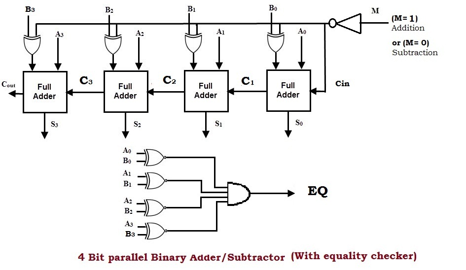
The operations of both addition and subtraction can be performed by one common binary adder. Such a binary circuit can be designed by adding an Ex-OR gate with each full adder as shown in the above figure. The figure above shows the 4-bit parallel binary adder/subtractor which has two 4 bit inputs as A(A3A2A1A0)and B(B3B2B1B0).
The mode input control line M is connected with carry input of the least significant bit of the full adder. This control line decides the type of operation, whether addition or subtraction.
When M=0 (internally circuit gets = 1), the circuit is a subtractor and when M=1 (internally circuit gets = 0), the circuit becomes an adder. The Ex-OR gate consists of two inputs to which one is connected to the B and other to input M.
When M = 1 (internally circuit gets = 0), B Ex-OR of 0 produces B. Then full adders add the B with A with carry input zero and hence an addition operation is performed.
When M =0 (internally circuit gets = 1), B Ex-OR of 1 produce B complement and also carry input is 1. Hence the complemented B inputs are added to A and 1 is added through the input carry, nothing but a 2’s complement operation. Therefore, the subtraction operation is performed.

Step by step
Solved in 3 steps with 1 images


