Introductory Circuit Analysis (13th Edition)
13th Edition
ISBN: 9780133923605
Author: Robert L. Boylestad
Publisher: PEARSON
expand_more
expand_more
format_list_bulleted
Question

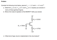
Transcribed Image Text:Problem
Consider the following circuit below, assume V
=
1.2 V and k = 0.5 mA/V².
th
a. Determine I (in mA), VGS (in V) and VDs (in V). Express your answers in
DS
terms of three significant figures.
b. What is the mode of operation of the MOSFET? Verify your answer.
5V
R₂ = 8.2k
R1 = 50kΩ
R3 = 4.7k
-5V
d. What kind of logic circuit is implemented in the circuit above?
I
Expert Solution
This question has been solved!
Explore an expertly crafted, step-by-step solution for a thorough understanding of key concepts.
This is a popular solution
Trending nowThis is a popular solution!
Step by stepSolved in 10 steps with 10 images

Knowledge Booster
Learn more about
Need a deep-dive on the concept behind this application? Look no further. Learn more about this topic, electrical-engineering and related others by exploring similar questions and additional content below.Similar questions
- i.... will give upvote if correctarrow_forwardIn the circuit given in the figure VT = 25mV, | VBE | = 0.7V, R1 = 950.31Kohm, R2 = 22.50Kohm, R3 = 2.51Kohm, R4 = 1.08Kohm, VCC = 13.00V, VEE = 3.00V, VA = 13.08V, Beta Since = 193.00, Rs = 22.94ohm, Ry = 14.49Kohm, calculate the IC current, Ri, R0 and the voltage gain according to the Source (V0 / V1) by making full analysis. When making your transactions, 2 steps will be taken after the point. Select the closest option according to +/- 10% margin of error. There is only one correct answer to the question.arrow_forward1-) With a +5 V (dc) common mode signal at the input of the circuit in the figure. There is a difference signal in the form of Vdiff = VI1-VI2 = 10*sin (wt) mv. Other in the circuit Assuming the values of the elements (2R1) = 1 ko, R2 = 0.5 MQ, and R3 = R4 = 10 ko, Calculate the voltage values at each node (7 nodes) shown in the figure. A1 RA R2 R3 2R| R3 A3 +. R2 On R4 A2 Un Oarrow_forward
- For the circuit shown in Figure If Vec= 35 v, Is= 3.88mA. 30oksr Vs = (dg) Veco 3 RE find VRC and VRB and RE and value of Betaarrow_forwardConsider the buck converter in Figure 5, with a DC voltage source, Vg = 100V and a load resistance, R equals to 2002. It is required that this converter delivers at least 100W to the load (output power). Assume the switching frequency is 100 kHz. Q₁ L 000 + i(t) D₁ C R>V iD(t) Figure 5 Determine the following: i. Critical value of the inductor, Lcrit ii. Converter voltage gain for inductor value, L = 0.1x Lcritarrow_forward@sync1arrow_forward
- In the circuit given in the figure VT = 25mV, | VBE | = 0.7V, R1 = 515.22Kohm, R2 = 10.89Kohm, R3 = 2.41Kohm, R4 = 1.03Kohm, VCC = 12.00V, VEE = 2.00V, VA = 12.51V, Beta Since = 107.00, Rs = 23.19ohm, Ry = 8.18Kohm, calculate the IC current, Ri, R0 and voltage gain according to the Source (V0 / V1) by making full analysis.arrow_forwardA buck converter operating in continues mode has the following parameters: Imin =0.9 A, Pout 124 W, R=2.6 2, f= 250 Hz, and the average value of the input current = 1.8 A. %3D %3D Find The inductor L in mH.arrow_forwardPlease answer in typing format please ASAP for the like please clear the solution of above question is given to the solution of above question Pleasearrow_forward
- 6. For the following circuit, calculate the required capacitor and resistor combination to limit the rate of change of voltage (dv/dt) across the SCR to 20V/us. Vin - 480Vrms, VORM 800V and di/dt rating is 48A/us. What is the outlined circuit called and what is its purpose? W VSIN R₂ www 100arrow_forwardHow can you produce one sideband only? Suggest a method to obtain SSB.arrow_forward
arrow_back_ios
arrow_forward_ios
Recommended textbooks for you
 Introductory Circuit Analysis (13th Edition)Electrical EngineeringISBN:9780133923605Author:Robert L. BoylestadPublisher:PEARSON
 Delmar's Standard Textbook Of ElectricityElectrical EngineeringISBN:9781337900348Author:Stephen L. HermanPublisher:Cengage Learning
 Programmable Logic ControllersElectrical EngineeringISBN:9780073373843Author:Frank D. PetruzellaPublisher:McGraw-Hill Education
 Fundamentals of Electric CircuitsElectrical EngineeringISBN:9780078028229Author:Charles K Alexander, Matthew SadikuPublisher:McGraw-Hill Education
 Electric Circuits. (11th Edition)Electrical EngineeringISBN:9780134746968Author:James W. Nilsson, Susan RiedelPublisher:PEARSON
 Engineering ElectromagneticsElectrical EngineeringISBN:9780078028151Author:Hayt, William H. (william Hart), Jr, BUCK, John A.Publisher:Mcgraw-hill Education,

Introductory Circuit Analysis (13th Edition)
Electrical Engineering
ISBN:9780133923605
Author:Robert L. Boylestad
Publisher:PEARSON

Delmar's Standard Textbook Of Electricity
Electrical Engineering
ISBN:9781337900348
Author:Stephen L. Herman
Publisher:Cengage Learning

Programmable Logic Controllers
Electrical Engineering
ISBN:9780073373843
Author:Frank D. Petruzella
Publisher:McGraw-Hill Education

Fundamentals of Electric Circuits
Electrical Engineering
ISBN:9780078028229
Author:Charles K Alexander, Matthew Sadiku
Publisher:McGraw-Hill Education

Electric Circuits. (11th Edition)
Electrical Engineering
ISBN:9780134746968
Author:James W. Nilsson, Susan Riedel
Publisher:PEARSON

Engineering Electromagnetics
Electrical Engineering
ISBN:9780078028151
Author:Hayt, William H. (william Hart), Jr, BUCK, John A.
Publisher:Mcgraw-hill Education,