
Introductory Circuit Analysis (13th Edition)
13th Edition
ISBN: 9780133923605
Author: Robert L. Boylestad
Publisher: PEARSON
expand_more
expand_more
format_list_bulleted
Related questions
Question
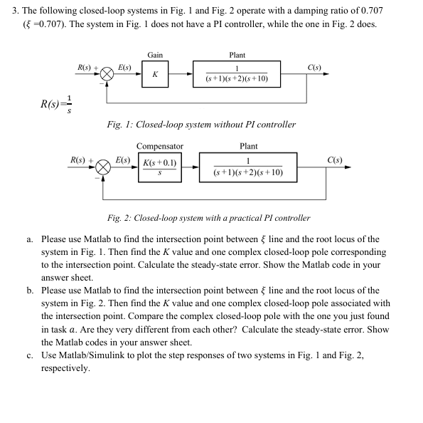

Transcribed Image Text:3. The following closed-loop systems in Fig. 1 and Fig. 2 operate with a damping ratio of 0.707
(=0.707). The system in Fig. 1 does not have a PI controller, while the one in Fig. 2 does.
R(s):
S
Gain
Plant
R(s) +
E(s)
1
C(s)
K
(s+1)(s+2)(s+10)
Fig. 1: Closed-loop system without PI controller
Compensator
Plant
R(s) +
E(s)
K(s+0.1)
S
1
(s+1)(s+2)(s+10)
C(s)
Fig. 2: Closed-loop system with a practical PI controller
a. Please use Matlab to find the intersection point between line and the root locus of the
system in Fig. 1. Then find the K value and one complex closed-loop pole corresponding
to the intersection point. Calculate the steady-state error. Show the Matlab code in your
answer sheet.
b. Please use Matlab to find the intersection point between § line and the root locus of the
system in Fig. 2. Then find the K value and one complex closed-loop pole associated with
the intersection point. Compare the complex closed-loop pole with the one you just found
in task a. Are they very different from each other? Calculate the steady-state error. Show
the Matlab codes in your answer sheet.
c. Use Matlab/Simulink to plot the step responses of two systems in Fig. 1 and Fig. 2,
respectively.
Expert Solution
This question has been solved!
Explore an expertly crafted, step-by-step solution for a thorough understanding of key concepts.

Step by stepSolved in 2 steps with 2 images

Knowledge Booster

Similar questions
- The statements given below in terms of linearity, time invariance and causality classify. Y1 (n) = 5x(n) + 2x²(n) y2(n) = x(n – 1) – 2x(n – 1)arrow_forwardHi there, this question is for control systems. Could I get help in completing it? Thanks.arrow_forwardI. From the given block diagram below, find the following: a) the total output of the system. b) the error ratio due to R₂. c) the differential equation due to R₁. d) the characteristic equation of the system. s + 1 R₁ + + R3 35² 4 2s - 1 + - 1/s s - 1 1/s² R₂ 2/sarrow_forward
- en the following circuit below, at t = 0 the switch closes: R₁ m R3 m + Vs Vs = 18V X t=0 m R₂ R₁ = 3kn R4 = 6kN 6ΚΩ C = R₂ 6ΚΩ C = 100µF R3 = vo(t) + M 12ΚΩ RA Use the differential equation method to determine the output voltagearrow_forwardAre the following statements true or false? T or F A) Any graph with an Euler trail that is not an Euler circuit can be made into a graph with an Euler circuit by adding a single edge. T or F B) If a graph has an Euler trail but not an Euler circuit, then every Euler trail must start at a vertex of odd degree. T or F C) If a complte graph has an Euler circuit, then the graph has an odd number of vertices. T or F D) Every graph in which every vertex has even degree has an Euler circuit. T or F E) Every graph with an Euler trail is connected.arrow_forwardThanksarrow_forward
- Consider the RLC circuit shown below; 1- write the state space description only. 2- Classify the RLC circuit according to Model. İL2 12 A 4 Ohm İL1 ic L1 1 H L2 2H Vo 1 F X₁=Vc X₂=İLL X3=iL2arrow_forwardThevenin's theorem states that a complex linear network with a pair of output terminals can be represented by this: a) A voltage source of value Vth (Thevenin equivalent voltage) in series with Rth (Thevenin equivalent resistance). b) A voltage source of value Vth (Thevenin equivalent voltage) in parallel with Rth (Thevenin equivalent resistance). c) A series RLC circuit d) Two fireflies O a O c d barrow_forwardAnalyze a series RLC circuit like the figure given below and find the equation for VR1 in terms of other components (not with their numerical values, just symbolic equation) 1.. C1 = 16 L1 =.. 26 R1 = 100 Q C1 L1 'R1 V1arrow_forward
arrow_back_ios
SEE MORE QUESTIONS
arrow_forward_ios
Recommended textbooks for you
- Introductory Circuit Analysis (13th Edition)Electrical EngineeringISBN:9780133923605Author:Robert L. BoylestadPublisher:PEARSON
 Delmar's Standard Textbook Of ElectricityElectrical EngineeringISBN:9781337900348Author:Stephen L. HermanPublisher:Cengage Learning
 Programmable Logic ControllersElectrical EngineeringISBN:9780073373843Author:Frank D. PetruzellaPublisher:McGraw-Hill Education
  Fundamentals of Electric CircuitsElectrical EngineeringISBN:9780078028229Author:Charles K Alexander, Matthew SadikuPublisher:McGraw-Hill Education
 Electric Circuits. (11th Edition)Electrical EngineeringISBN:9780134746968Author:James W. Nilsson, Susan RiedelPublisher:PEARSON
 Engineering ElectromagneticsElectrical EngineeringISBN:9780078028151Author:Hayt, William H. (william Hart), Jr, BUCK, John A.Publisher:Mcgraw-hill Education,
Introductory Circuit Analysis (13th Edition)
Electrical Engineering
ISBN:9780133923605
Author:Robert L. Boylestad
Publisher:PEARSON
Delmar's Standard Textbook Of Electricity
Electrical Engineering
ISBN:9781337900348
Author:Stephen L. Herman
Publisher:Cengage Learning
Programmable Logic Controllers
Electrical Engineering
ISBN:9780073373843
Author:Frank D. Petruzella
Publisher:McGraw-Hill Education
Fundamentals of Electric Circuits
Electrical Engineering
ISBN:9780078028229
Author:Charles K Alexander, Matthew Sadiku
Publisher:McGraw-Hill Education
Electric Circuits. (11th Edition)
Electrical Engineering
ISBN:9780134746968
Author:James W. Nilsson, Susan Riedel
Publisher:PEARSON
Engineering Electromagnetics
Electrical Engineering
ISBN:9780078028151
Author:Hayt, William H. (william Hart), Jr, BUCK, John A.
Publisher:Mcgraw-hill Education,