
Structural Analysis
6th Edition
ISBN: 9781337630931
Author: KASSIMALI, Aslam.
Publisher: Cengage,
expand_more
expand_more
format_list_bulleted
Related questions
Concept explainers
Question
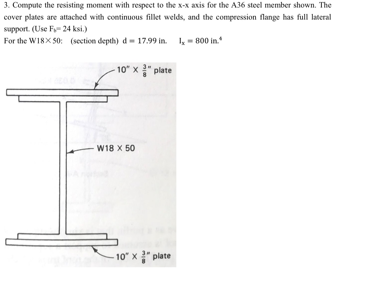

Transcribed Image Text:3. Compute the resisting moment with respect to the x-x axis for the A36 steel member shown. The
cover plates are attached with continuous fillet welds, and the compression flange has full lateral
support. (Use F1= 24 ksi.)
For the W18X 50: (section depth) d = 17.99 in.
Ix
= 800 in 4
10" x " plate
W18 X 50
10" X" plate
![Appendix
Expressions for axially loaded compression member:
KI
For-< C. =
2T²E
[1 – (Kl/r)²/(2C? )]Fy
F, =
5 3(Kl/r) _ (Kl/r)³
8Cc
Fy
|21²E
1212E
KI
For-> Cc
Fa
Fy
23(KI/r)2
Pa =
FaA
Expressions for beam:
MR = F,S, in which S =-
Expressions for tension member:
Pt = A,F , in which F = 0.6Fy
P; = A,Ft , in which F = 0.5Fu
P = A.Ft , in which Ae = U An, F = 0.5Fu
P = A,F, + A,F; , in which Fy = 0.30Fµ , F; = 0.50Fu
P = nr,, in which r, = ApFv, ry = d t F,
TABLE 2-1 Values for Reduction Coefficient, U
U = 0.90
W, M, S shapes or their tees.
Connection is to the flanges.
Minimum of three bolts per line in the direction of
Case I
stress.
(min.)
(min.)
U = 0,85
All shapes and built-up cross sections not meeting
the requirements of case I. Minimum of three bolts
per line in the direction of stress.
Case II
U = 0.75
All members whose connections have only two bolts
per line in the direction of stress.
Case III
Units:
ksi : kips per square inch
kips: kilo pounds
lb/ft: pounds per foot
kips/ft: kilo pounds per foot](https://content.bartleby.com/qna-images/question/20cba98e-6744-4650-af87-e93c56f86f12/84935fd2-3b26-4958-94d5-7dca8dab4676/2q6daw_processed.jpeg)
Transcribed Image Text:Appendix
Expressions for axially loaded compression member:
KI
For-< C. =
2T²E
[1 – (Kl/r)²/(2C? )]Fy
F, =
5 3(Kl/r) _ (Kl/r)³
8Cc
Fy
|21²E
1212E
KI
For-> Cc
Fa
Fy
23(KI/r)2
Pa =
FaA
Expressions for beam:
MR = F,S, in which S =-
Expressions for tension member:
Pt = A,F , in which F = 0.6Fy
P; = A,Ft , in which F = 0.5Fu
P = A.Ft , in which Ae = U An, F = 0.5Fu
P = A,F, + A,F; , in which Fy = 0.30Fµ , F; = 0.50Fu
P = nr,, in which r, = ApFv, ry = d t F,
TABLE 2-1 Values for Reduction Coefficient, U
U = 0.90
W, M, S shapes or their tees.
Connection is to the flanges.
Minimum of three bolts per line in the direction of
Case I
stress.
(min.)
(min.)
U = 0,85
All shapes and built-up cross sections not meeting
the requirements of case I. Minimum of three bolts
per line in the direction of stress.
Case II
U = 0.75
All members whose connections have only two bolts
per line in the direction of stress.
Case III
Units:
ksi : kips per square inch
kips: kilo pounds
lb/ft: pounds per foot
kips/ft: kilo pounds per foot
Expert Solution
This question has been solved!
Explore an expertly crafted, step-by-step solution for a thorough understanding of key concepts.

Step by stepSolved in 2 steps with 3 images

Knowledge Booster


Learn more about
Need a deep-dive on the concept behind this application? Look no further. Learn more about this topic, civil-engineering and related others by exploring similar questions and additional content below.Similar questions
- A W14X120 is used as a tension member in atruss. The flanges of the member are connected to a gusset plate by 3/4 inch boltas shown below. Use A36 steel with Fy-36 ksi and Fu=58 ksi Determine the Yielding Capacity of the section based on LRFD (kips) Determine the Tensile Rupture capacity of the section based on LRFD Determine the Demand to Governing Capacity Ratio (based on yielding and rupture only) if the Demand load carried by the section are DL=200 kips LL=400 kips use LRFD Properties and Dimension Ag=35.30 in^2 x = 6.24 in ry= 3.74 in d=14.5 in tf=0.94 in bf=14.7 in tw=0.59 in k=1.54 d=14.5 Y k1=1.5 bf=14.7 tf-0.94 X -tw=0.59 Harrow_forwardThe welded frame beam connection consists of the framing angle 100 x 75 x12.5mm and the column W12 x 72. The welds are 9mm fillet welds made with E70 electrodes. All members are A36 steel. 12.5 mm a.) Determine Pu base on the capacity of the welds. Use LRFD design Factors. W 12x72 Angular Section 75 m 18.75 18.75 Angular section Angular section 800arrow_forwardSelect the lightest C6 channel shape to be used as a 12 ft long tension member to resist the following service loads, PD = 20 k and P₁ = 32 k. The member will be con- nected by a transverse weld at the end of the channel only. Use A36 Grade 36 steel with F = 58 ksi. (Ans. C6 × 10.5 LRFD and ASD)arrow_forward
- please solve 1.3arrow_forwardA welded tension member is consisting of two channels placed 400mm back to back with flanges turned out. Select a channel for factored tensile of 4RKN using A36 steel and AISC specifications.The member is to be 15m long. Take R= 433.5 Factored design load= R*4arrow_forward34. Determine the available strength of a WT7×15, A992 steel, with the flanges welded to a 1/2 in. gusset plate by a 10 in. weld along each side of the flange. Considering yielding and net section rupture, determine the (a) design strength by LRFD and (b) allowable strength by ASD.arrow_forward
arrow_back_ios
arrow_forward_ios
Recommended textbooks for you
 Structural Analysis (10th Edition)Civil EngineeringISBN:9780134610672Author:Russell C. HibbelerPublisher:PEARSON
 Principles of Foundation Engineering (MindTap Cou...Civil EngineeringISBN:9781337705028Author:Braja M. Das, Nagaratnam SivakuganPublisher:Cengage Learning
 Fundamentals of Structural AnalysisCivil EngineeringISBN:9780073398006Author:Kenneth M. Leet Emeritus, Chia-Ming Uang, Joel LanningPublisher:McGraw-Hill Education
 Traffic and Highway EngineeringCivil EngineeringISBN:9781305156241Author:Garber, Nicholas J.Publisher:Cengage Learning
Structural Analysis (10th Edition)
Civil Engineering
ISBN:9780134610672
Author:Russell C. Hibbeler
Publisher:PEARSON
Principles of Foundation Engineering (MindTap Cou...
Civil Engineering
ISBN:9781337705028
Author:Braja M. Das, Nagaratnam Sivakugan
Publisher:Cengage Learning
Fundamentals of Structural Analysis
Civil Engineering
ISBN:9780073398006
Author:Kenneth M. Leet Emeritus, Chia-Ming Uang, Joel Lanning
Publisher:McGraw-Hill Education
Traffic and Highway Engineering
Civil Engineering
ISBN:9781305156241
Author:Garber, Nicholas J.
Publisher:Cengage Learning