Delmar's Standard Textbook Of Electricity
7th Edition
ISBN: 9781337900348
Author: Stephen L. Herman
Publisher: Cengage Learning
expand_more
expand_more
format_list_bulleted
Concept explainers
Question

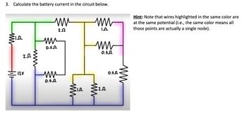
Transcribed Image Text:3. Calculate the battery current in the circuit below.
www
ww
пи
0.5.2
252
ww
In
ww
0.52
Hint: Note that wires highlighted in the same color are
at the same potential (i.e., the same color means all
those points are actually a single node).
202
wwww
12V
ww
0.502
ww
5
ww
20
0.5.
Expert Solution
This question has been solved!
Explore an expertly crafted, step-by-step solution for a thorough understanding of key concepts.
Step by stepSolved in 5 steps with 5 images

Knowledge Booster
Learn more about
Need a deep-dive on the concept behind this application? Look no further. Learn more about this topic, electrical-engineering and related others by exploring similar questions and additional content below.Similar questions
- Typing format..arrow_forwardQ2) For the circuits in the figure below a) Explain the work of the cct. In the figure (a) and explain how lamp will lighting, b) Explain the work of the cct. In the figure (b) and explain how LED will lighting. Input 356 V+ 15 V) (a) 30 mA www 1000 600 mA (220) V+Vi Input 358 (b) 20 mA www 1800arrow_forwardWhat is the difference between a current source and current sink draw diagrams aswell to explain.arrow_forward
- Question 5 a) For a DC Power Supply, having a voltage of 50 V, design circuits which can give the following output voltages: i) 10 Volts ii) 25 Volts iii) 45 Volts Draw the labelled circuit diagram for each output voltage value and show calculations for all. Use R1 = 4.7 kQ for one of the resistance Hint: Use voltage divider circuits, you can use any value of resistances you like.arrow_forwardThese Insulators are used when equal Voltage is required across each Insulator unit. O A. RADING INSULATORS O B. GRADING INSULATORS O C. STRAINING INSULATORS O D. GAINING INSULATORSarrow_forwardHi, can you help me with this whole question please. Thank youarrow_forward
- only 11arrow_forwardFor an RTD the relationship between resistance and temperature is a. proportional b. no relation c. equal d. inversely proportionalarrow_forwardWhere is the best place in a circuit to find absolute zero when measuring voltage? O At the negative terminal of the battery. O At the positive terminal of the battery. O At either side of the circuit protection device. O On the ground side of the load device. orearrow_forward
- 3. The figure on the left below shows a schematic diagram of a battery. The voltage measured by U1 is called the terminal voltage given R1 = 1 ohm. In the figure on the right below, the terminal voltage of each of the battery-resistor combination is Vr = 1.5 volts. Find the following: a. The current passing through R5. b. The currents passing through R1 and R3 C. The voltage across R1. d. The voltage of the battery EMF. e. The percentage of voltage loss ot the battery due to the internal resistance R1. The power dissipated by the internal resistance R1. g. The power dissipated by R5 if R1 = R2 = R3 = R4 = 0. h. The percentage of power dissipation loss due to the four resistors R1, R2, R3, and R4 f. R1 R3 S10 R1 U1 1.500 EMF EMF R5 100 V1 R2 $10 EMF R4 EMF EMFarrow_forward2. In the previous diagram for an LED circuit, the power supply is a 9V battery and we are using a Red LED whose voltage drop is 2V. The specification sheet for the LED recommends that the "ON" current should be 10 milliamps. a. What series resistor will give the specified LED current? 7737-1 C. b. What is the power dissipated by the resistor you selected in part a? A 70 2 What is the power dissipated in the LED?arrow_forwardX & DA G F2 a) For a DC Power Supply, having a voltage of 50 V, design circuits which can give the following output voltages: i) 10 Volts ii) 25 Volts iii) 45 Volts Draw the labelled circuit diagram for each output voltage value and show calculations for all. Use R1 = 4.7 kQ for one of the resistance Hint: Use voltage divider circuits, you can use any value of resistances you like. Local backup on b) Calculate the Total equivalent resistance (RT) for the circuit shown in figure 4 and draw the equivalent circuit replacing the whole network with just one Resistance (RT): 80 F3 R1 ww 1 4.1kΩ R3 2 www R2 dan 2.00ΜΩ 10092 R7 1 MQ Q F4 V1 5V 4 First Line Indent: 0 U F5 Figure 4 F6 3 R4 33092 R6 www 59092 5 F7 Exit R5 470 kQ DII F8 H 00 F9 Harrow_forward
arrow_back_ios
SEE MORE QUESTIONS
arrow_forward_ios
Recommended textbooks for you
 Delmar's Standard Textbook Of ElectricityElectrical EngineeringISBN:9781337900348Author:Stephen L. HermanPublisher:Cengage Learning

Delmar's Standard Textbook Of Electricity
Electrical Engineering
ISBN:9781337900348
Author:Stephen L. Herman
Publisher:Cengage Learning
