
Elements Of Electromagnetics
7th Edition
ISBN: 9780190698614
Author: Sadiku, Matthew N. O.
Publisher: Oxford University Press
expand_more
expand_more
format_list_bulleted
Related questions
Question
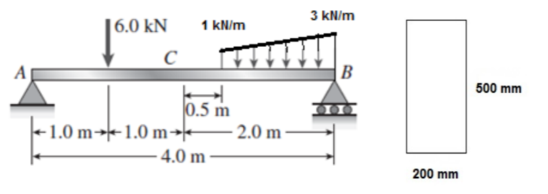
The simple beam AB, shown below, supports a concentrated load of 6 kN and a segment
of non-uniform load of intensity varies from 1 kN/m to 3 kN/m at point B.
a). Determine the maximum bending stress and the maximum shear stress acting on the beam if the beam has a rectangular cross section of (500 mm × 200 mm).

Transcribed Image Text:3 kN/m
|6.0 kN
1 kN/m
B
500 mm
0.5 m
+1.0 m→1.0 m→*
– 4.0 m
2.0 m
200 mm
Expert Solution
This question has been solved!
Explore an expertly crafted, step-by-step solution for a thorough understanding of key concepts.

Step by stepSolved in 4 steps with 7 images

Knowledge Booster


Learn more about
Need a deep-dive on the concept behind this application? Look no further. Learn more about this topic, mechanical-engineering and related others by exploring similar questions and additional content below.Similar questions
- The cantilever beam AC shown in the figure is subjected to a load 1kN at the end A, and an in- plane clockwise moment 5 kNm at B. The shear force and bending moment in the beam at C are respectively, 1 kN 2 m 3 m O a. (-)1 kN, 0 Ob. 1 kN, 5 kNm OC. 1 kN, (-)5 kNm Od. (-)1 kN, 10 kNmarrow_forwardDetermine the maximum bending stress (in psi) in the beam and its location as generated from the loading condition with the beam cross-section shown below. 2 kip/ft -5 ft- -5 ft 30 kip-ft -5 ft- B 12"- 6" AXarrow_forwardDetermine the maximum bending moment magnitude for the beam shown below. Use a = 16 ft, b = 6 ft, and w = 10 kips/ft. The reaction forces for this beam are Ay = 68.7 kips and By = 151.2 kips. B |C a b. Answer: Mmax = i kip-ftarrow_forward
- Use Singularity functions to draw the shear and bending moment diagram for this beam problem in terms of F and L.arrow_forwardFor the eccentric loaded beam shown, determine the following:(a)Calculate the axial stress(b)Calculate the bending stress in the top and bottom layers of the beam(C)Determine the combined stress and sketch the combined stress profile in the beam sectionarrow_forwardThe cross-sectional dimensions of a beam are shown. Assume b=3 in., tetw=0.4375 in. and d=3.375 in. (a) If the bending stress at point K is 1860 psi (T), determine the internal bending moment M, acting about the z centroidal axis of the beam. (b) Determine the bending stress oH at point H (positive if tension, negative if compression). K d H bf Answers: (a) M2 = i Ib-ft. ( b) σμ i psi. %3D Save for Later Attempts: 0 of 1 used Submit Answerarrow_forward
- A beam is subjected to equal 21.7 kip-ft bending moments. Assume t₁ =t₂ = tw- 3 in., d = 15 in., b₁ = 6 in., and b₂ =8 in. The cross- sectional dimensions of the beam are illustrated. Determine: (a) the distance y to the centroid (measured from the bottom), the moment of inertial₂ about the z axis, and the controlling section modulus S₂ about the z axis. (b) the bending stress at point H (positive if tension, negative if compression). (c) the bending stress ok at point K(positive if tension, negative if compression). (d) the maximum bending stress max produced in the cross section (positive if tension, negative if compression). M Answers: (a) y = (b) 6μ = 6.978 (c) OK (c) omax = = i M in., I₂ = X i psi. psi. psi. 41 1₂ 2886.59 b₁ b₂ Cross section H K in.4, S₂ = i in.³.arrow_forward1. For the beam shown and given cross-section determine the maximum bending stress and the absolute maximum bending stress. 2. Determine the maximum shear stress in the beamarrow_forwardI have gotten this question wrong twice, so the answer isn't 3.43 or .413 kN/m.arrow_forward
arrow_back_ios
arrow_forward_ios
Recommended textbooks for you
- Elements Of ElectromagneticsMechanical EngineeringISBN:9780190698614Author:Sadiku, Matthew N. O.Publisher:Oxford University Press
 Mechanics of Materials (10th Edition)Mechanical EngineeringISBN:9780134319650Author:Russell C. HibbelerPublisher:PEARSON
 Thermodynamics: An Engineering ApproachMechanical EngineeringISBN:9781259822674Author:Yunus A. Cengel Dr., Michael A. BolesPublisher:McGraw-Hill Education
  Control Systems EngineeringMechanical EngineeringISBN:9781118170519Author:Norman S. NisePublisher:WILEY
 Mechanics of Materials (MindTap Course List)Mechanical EngineeringISBN:9781337093347Author:Barry J. Goodno, James M. GerePublisher:Cengage Learning
 Engineering Mechanics: StaticsMechanical EngineeringISBN:9781118807330Author:James L. Meriam, L. G. Kraige, J. N. BoltonPublisher:WILEY
Elements Of Electromagnetics
Mechanical Engineering
ISBN:9780190698614
Author:Sadiku, Matthew N. O.
Publisher:Oxford University Press
Mechanics of Materials (10th Edition)
Mechanical Engineering
ISBN:9780134319650
Author:Russell C. Hibbeler
Publisher:PEARSON
Thermodynamics: An Engineering Approach
Mechanical Engineering
ISBN:9781259822674
Author:Yunus A. Cengel Dr., Michael A. Boles
Publisher:McGraw-Hill Education
Control Systems Engineering
Mechanical Engineering
ISBN:9781118170519
Author:Norman S. Nise
Publisher:WILEY
Mechanics of Materials (MindTap Course List)
Mechanical Engineering
ISBN:9781337093347
Author:Barry J. Goodno, James M. Gere
Publisher:Cengage Learning
Engineering Mechanics: Statics
Mechanical Engineering
ISBN:9781118807330
Author:James L. Meriam, L. G. Kraige, J. N. Bolton
Publisher:WILEY