Structural Analysis
6th Edition
ISBN: 9781337630931
Author: KASSIMALI, Aslam.
Publisher: Cengage,
expand_more
expand_more
format_list_bulleted
Concept explainers
Question
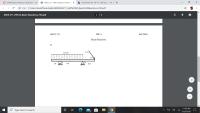
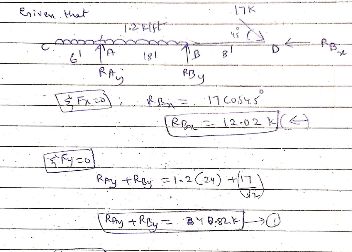
Determine the Reactions of the beam. Show the Distributed Load Resultant magnitude and location on the loading diagram.

Transcribed Image Text:3)
1.2 k/ft
17 k
450
А
6 ft
В
8 ft
18 ft
Expert Solution
arrow_forward
Step 1
Reactions

Step by stepSolved in 2 steps with 2 images

Knowledge Booster
Learn more about
Need a deep-dive on the concept behind this application? Look no further. Learn more about this topic, civil-engineering and related others by exploring similar questions and additional content below.Similar questions
- is strengthened by bolting two cover The wide-flange beam shown in Fig. plates 160 mm by 20 mm to the top and bottom flanges. If the maximum flexure stress is 140 MPa, compute the total force (a) in each cover plate and (b) in each flange. Neglect the weakening effect of the bolt holes. 160 mm 20 mm 20 mm 320 mm 20 mm €20 mmarrow_forwardGiven: picture. Find: determine the reactions at the beam supports at A& D for the given loading.arrow_forwardA wooden frame shown below is supported by a tie rod CF and a pin support at A. The diameter of the tie rod CF is 30 mm, and the cross-sectional area of member BD is 900 mm?. The diameters of the pins at A and D are 8 mm and 12 mm, respectively, and each pin is subjected to double shear. If the weight of the bucket hanging from end E is 3 kN, determine (a) The axial stresses in tie rod CF and member BD. (b) The shear stresses in pins A and D. - 0.6 m-0.6 m→ D E 0.6 m V30B 1.2 m Farrow_forward
- A square bar carries a series of loads as shown in Figure P1-47. Compute the stress in each segment of the bar. All loads act along the central axis of 1-47. the bar.arrow_forwardPls ans within 10 minsarrow_forwardThe shown L-shape cantilver is loaded as shown and fixed at A. It has a constant section of 40 mm X 20 mm. For point I located at 50 mm from support A, at the midheight of the section, determine the principal stresses, the principal planes and the maximum shear stress. y 50 mm 150 mm 40 mm 0.5 kN H- I 20 mm 3 kN 160 mm 2.5 kNarrow_forward
arrow_back_ios
arrow_forward_ios
Recommended textbooks for you

 Structural Analysis (10th Edition)Civil EngineeringISBN:9780134610672Author:Russell C. HibbelerPublisher:PEARSON
 Principles of Foundation Engineering (MindTap Cou...Civil EngineeringISBN:9781337705028Author:Braja M. Das, Nagaratnam SivakuganPublisher:Cengage Learning
 Fundamentals of Structural AnalysisCivil EngineeringISBN:9780073398006Author:Kenneth M. Leet Emeritus, Chia-Ming Uang, Joel LanningPublisher:McGraw-Hill Education
 Traffic and Highway EngineeringCivil EngineeringISBN:9781305156241Author:Garber, Nicholas J.Publisher:Cengage Learning


Structural Analysis (10th Edition)
Civil Engineering
ISBN:9780134610672
Author:Russell C. Hibbeler
Publisher:PEARSON

Principles of Foundation Engineering (MindTap Cou...
Civil Engineering
ISBN:9781337705028
Author:Braja M. Das, Nagaratnam Sivakugan
Publisher:Cengage Learning

Fundamentals of Structural Analysis
Civil Engineering
ISBN:9780073398006
Author:Kenneth M. Leet Emeritus, Chia-Ming Uang, Joel Lanning
Publisher:McGraw-Hill Education


Traffic and Highway Engineering
Civil Engineering
ISBN:9781305156241
Author:Garber, Nicholas J.
Publisher:Cengage Learning