
Mechanics of Materials (MindTap Course List)
9th Edition
ISBN: 9781337093347
Author: Barry J. Goodno, James M. Gere
Publisher: Cengage Learning
expand_more
expand_more
format_list_bulleted
Related questions
Question
thumb_up100%
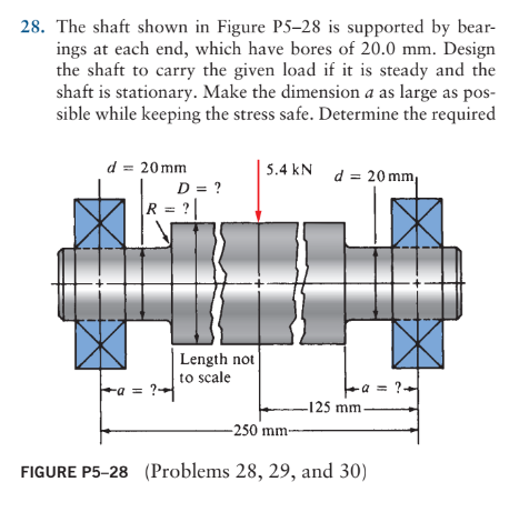

Transcribed Image Text:28. The shaft shown in Figure P5-28 is supported by bear-
ings at each end, which have bores of 20.0 mm. Design
the shaft to carry the given load if it is steady and the
shaft is stationary. Make the dimension a as large as pos-
sible while keeping the stress safe. Determine the required
d = 20mm
D = ?
R = ?|
5.4 kN d=20mm
Length not
to scale
-a = ?-
+а=
a = ? +
-125 mm-
-250 mm-
FIGURE P5-28 (Problems 28, 29, and 30)
Expert Solution
This question has been solved!
Explore an expertly crafted, step-by-step solution for a thorough understanding of key concepts.

Step by stepSolved in 2 steps with 1 images

Knowledge Booster

Similar questions
- 28. The shaft shown in Figure P5-28 is supported by bear- ings at each end, which have bores of 20.0 mm. Design the shaft to carry the given load if it is steady and the shaft is stationary. Make the dimension a as large as pos- sible while keeping the stress safe. Determine the required d = 20mm D = ? R = ?| 5.4 kN d=20mm Length not to scale -a = ?- +а= a = ? + -125 mm- -250 mm- FIGURE P5-28 (Problems 28, 29, and 30)arrow_forward28. The shaft shown in Figure P5-28 is supported by bear- ings at each end, which have bores of 20.0 mm. Design the shaft to carry the given load if it is steady and the shaft is stationary. Make the dimension a as large as pos- sible while keeping the stress safe. Determine the required d 20 mm 5.4 kN d D = ? Length not to scale -α = = -125 mm 20 mm a = -250 mm- FIGURE P5-28 (Problems 28, 29, and 30)arrow_forward80mm Y SK 60mm V 120 mm Gomm 40mm ->; Statics -2x Criven the shape above, Find The location of the Controid. Show all work.arrow_forward
- A,B,C,D,E,F,G WHICH POINT PLS WRITE THE LETTER AS UR FINAL ANSWER THXarrow_forwardSolve with numerical stepsarrow_forwardRequired information The shaft shown in the figure is machined from AISI 1040 CD steel. The shaft rotates at 1600 rpm and is supported in rolling bearings at A and B. The applied forces are F₁ = 1600 lbf and F2 = 640 lbf. A steady torque of 1600 lbf-in is being transmitted through the shaft between the points of application of the forces. ↑ i 3 in- -10 in- F₁ ↑ in F₂ -10 in- All fillets in R. -8 in inៗ → p'in 3 in in B -3 NOTE: This is a multi-part question. Once an answer is submitted, you will be unable to return to this part. What is the factor of safety against fatigue at infinite life? Use the Goodman failure criterion. (You must provide an answer before moving to the next part.) The factor of safety against fatigue at infinite life isarrow_forward
- Direct a key d the Hub Shear plane Hub Key F2 y, or anical F1 T=Torque Shaft T=F(D/2) F = Force of shaft on key F= Force of hub on key Side view -D Shaft diameter End view Shear Shaft plane Hub F1 Key F2 Shear area = A, = bxL %3D Enlarged view of key Pictorial sketch of key, shaft, and hub Ноуarrow_forwardA gear reduction unit uses the countershaft shown in the figure. Gear A receives power from another gear with the transmitted force FA applied at the 20° pressure angle as shown. The power is transmitted through the shaft and delivered through gear B through a transmitted force Fg at the pressure angle shown. For the steel countershaft shown below, assume the bearings have a maximum slope specification of 0.062° for good bearing life. Check wether the shaft dia below meets the requirement. If not determine a suitable shaft diameter. 400 mm FB 350 mm 25° 300 mm FA = 11 kN• 20° 50-mm dia. Gear A, 600-mm dia. Gear B, 300-mm dia. mm. The minimum shaft diameter is determined to bearrow_forwardPlease help with all need items, analysis, element, mohir circle, wtc. Thank you.arrow_forward
arrow_back_ios
SEE MORE QUESTIONS
arrow_forward_ios
Recommended textbooks for you
- Mechanics of Materials (MindTap Course List)Mechanical EngineeringISBN:9781337093347Author:Barry J. Goodno, James M. GerePublisher:Cengage Learning
Mechanics of Materials (MindTap Course List)
Mechanical Engineering
ISBN:9781337093347
Author:Barry J. Goodno, James M. Gere
Publisher:Cengage Learning