
Introductory Circuit Analysis (13th Edition)
13th Edition
ISBN: 9780133923605
Author: Robert L. Boylestad
Publisher: PEARSON
expand_more
expand_more
format_list_bulleted
Related questions
Concept explainers
Question
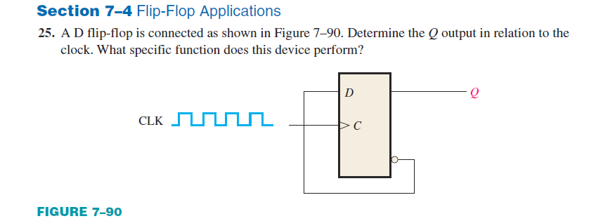

Transcribed Image Text:Section 7-4 Flip-Flop Applications
25. AD flip-flop is connected as shown in Figure 7–90. Determine the Q output in relation to the
clock. What specific function does this device perform?
D
CLK UUL
C
FIGURE 7-90
Expert Solution
This question has been solved!
Explore an expertly crafted, step-by-step solution for a thorough understanding of key concepts.

This is a popular solution

Trending nowThis is a popular solution!

Step by stepSolved in 2 steps with 1 images

Knowledge Booster


Learn more about
Need a deep-dive on the concept behind this application? Look no further. Learn more about this topic, electrical-engineering and related others by exploring similar questions and additional content below.Similar questions
- 2. Consider the following circuit D å lå a. Find the expressions for D, T, Qo*, Q₁*. b. Write the transition output table. c. Draw the state diagram of the circuit. d. Is this a Mealy or Moore machine? Explain. T 21 a la 1arrow_forwardLogic circuit Design combinational logic circuit that takes 7 bit numbers and an input and output will be the reverse of this bits from right to left to the first one including one and remaining of the bits will be the same example input 0011000 output 0010111 Can you draw it’s logic circuit in detail not theory answer and if we can solve this question multiplexerarrow_forwardQuestion 3 The 555 timer is connected in the following circuit. The resistance of the extra resistor is 102, the capacitance of the extra capacitor is 0.1F. The voltage input at Pin2 is Vcc. What is the output state at Pin3? 1) 2) Decide the voltage input value at Pin 6 when the condition is stable. 3) Decide the output state at Pin3 when a trigger input is applied at Pin2 (voltage input at Pin2 changes from Vcc to 0, and return back to Vcc immediately). 4) After the trigger input is applied at Pin2, how long would the output maintain at the unstable state. Vc R O Output Vo 555 Vc 0.01µF Trigger Inputarrow_forward
arrow_back_ios
arrow_forward_ios
Recommended textbooks for you
- Introductory Circuit Analysis (13th Edition)Electrical EngineeringISBN:9780133923605Author:Robert L. BoylestadPublisher:PEARSON
 Delmar's Standard Textbook Of ElectricityElectrical EngineeringISBN:9781337900348Author:Stephen L. HermanPublisher:Cengage Learning
 Programmable Logic ControllersElectrical EngineeringISBN:9780073373843Author:Frank D. PetruzellaPublisher:McGraw-Hill Education
  Fundamentals of Electric CircuitsElectrical EngineeringISBN:9780078028229Author:Charles K Alexander, Matthew SadikuPublisher:McGraw-Hill Education
 Electric Circuits. (11th Edition)Electrical EngineeringISBN:9780134746968Author:James W. Nilsson, Susan RiedelPublisher:PEARSON
 Engineering ElectromagneticsElectrical EngineeringISBN:9780078028151Author:Hayt, William H. (william Hart), Jr, BUCK, John A.Publisher:Mcgraw-hill Education,
Introductory Circuit Analysis (13th Edition)
Electrical Engineering
ISBN:9780133923605
Author:Robert L. Boylestad
Publisher:PEARSON
Delmar's Standard Textbook Of Electricity
Electrical Engineering
ISBN:9781337900348
Author:Stephen L. Herman
Publisher:Cengage Learning
Programmable Logic Controllers
Electrical Engineering
ISBN:9780073373843
Author:Frank D. Petruzella
Publisher:McGraw-Hill Education
Fundamentals of Electric Circuits
Electrical Engineering
ISBN:9780078028229
Author:Charles K Alexander, Matthew Sadiku
Publisher:McGraw-Hill Education
Electric Circuits. (11th Edition)
Electrical Engineering
ISBN:9780134746968
Author:James W. Nilsson, Susan Riedel
Publisher:PEARSON
Engineering Electromagnetics
Electrical Engineering
ISBN:9780078028151
Author:Hayt, William H. (william Hart), Jr, BUCK, John A.
Publisher:Mcgraw-hill Education,