
Introductory Circuit Analysis (13th Edition)
13th Edition
ISBN: 9780133923605
Author: Robert L. Boylestad
Publisher: PEARSON
expand_more
expand_more
format_list_bulleted
Related questions
Question
None

Transcribed Image Text:20
10V
2Ω
20
ΔΩ
AL
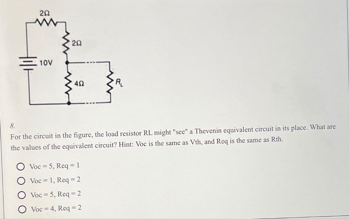
8.
For the circuit in the figure, the load resistor RL might "see" a Thevenin equivalent circuit in its place. What are
the values of the equivalent circuit? Hint: Voc is the same as Vth, and Req is the same as Rth.
Voc 5, Req=1
Voc 1, Req=2
Voc 5, Req=2
Voc 4, Req=2
Expert Solution
This question has been solved!
Explore an expertly crafted, step-by-step solution for a thorough understanding of key concepts.

Step by stepSolved in 2 steps with 3 images

Knowledge Booster

Similar questions
- What is the peak positive output voltage to the load resistor? (Units are in Volts.) What is the peak negative output voltage to the load resistor? (Units are in Volts.) Please in typing format please ASAP forarrow_forwardQuestion V.Full explain this question and text typing work only We should answer our question within 2 hours takes more time then we will reduce Rating Dont ignore this linearrow_forwardRc does not look like a standard resistor value? and what about choosing value for Re, it has to be standard value as wellarrow_forward
- How did they do KVL, really stuck with KVL so explain simply.arrow_forwardIn circuit shown in figure, the operating point is chosen such that Ic = 1.57 mA, VCE = 3.1V,If Rc = 2.5 KN, Vcc = 9 V and ß = 49 Determine the values of R1, R2 and Rɛ [VBE = 0.7 V and , = 106] RC R1 Vcc RE R2 Hobl- www www www wwwarrow_forwardVoltage Zener is used in the circuit below and the load current is to vary from 12 to 100 mA. Find the value of series resistance R and the range of load resistance to maintain a voltage of 7.2 V across the load. The input voltage is constant at 12V and the minimum Zener current is 10 mA. ... IL R Iz Eo RL Vz E, = 12 Varrow_forward
- Q3 Please respond to question in attached image please. Thank you.arrow_forwardNegative Clamping Circuit: Can you explain why the output voltage gets shifted down logically?arrow_forwardCalculate the dc and ac components of the output signal across load RL in the circuit of Figure * Vác = 150 V V, (ms) = 15 V V', (ms) R 500 2 C2 10μF Full-wave 15 μF 5 k2 rectifier Vdc= 136.4V, Vac= 3.9V Vdc= 163.4V, Vac= 9.3V Vdc= 13.4V, Vac= 9.9V None of the abovearrow_forward
- Don't know what these values are? What is H ? How can they add them?arrow_forwardRefer to the following figure. The circuit is a @ Battl www Oa. Positive limiter with positive bias O b. Negative clamper OC. Negative limiter with negative bias Od. Positive clamperarrow_forward2.0 a. TMP35 b. TMP36 c. TMP37 +Vs - 3V Using the appropriate curve, develop a linear equation for the output temperature as a function of voltage. 1.8 1.6 E 1.4 1.2 1.0 0.8 0.6 0.4 0.2 -50 -25 25 50 75 100 125 TEMPERATURE (*C) Figure 6. Output Voltage vs. Temperature OUTPUT VOLTAGE (V) 200-20C 00arrow_forward
arrow_back_ios
SEE MORE QUESTIONS
arrow_forward_ios
Recommended textbooks for you
- Introductory Circuit Analysis (13th Edition)Electrical EngineeringISBN:9780133923605Author:Robert L. BoylestadPublisher:PEARSON
 Delmar's Standard Textbook Of ElectricityElectrical EngineeringISBN:9781337900348Author:Stephen L. HermanPublisher:Cengage Learning
 Programmable Logic ControllersElectrical EngineeringISBN:9780073373843Author:Frank D. PetruzellaPublisher:McGraw-Hill Education
  Fundamentals of Electric CircuitsElectrical EngineeringISBN:9780078028229Author:Charles K Alexander, Matthew SadikuPublisher:McGraw-Hill Education
 Electric Circuits. (11th Edition)Electrical EngineeringISBN:9780134746968Author:James W. Nilsson, Susan RiedelPublisher:PEARSON
 Engineering ElectromagneticsElectrical EngineeringISBN:9780078028151Author:Hayt, William H. (william Hart), Jr, BUCK, John A.Publisher:Mcgraw-hill Education,
Introductory Circuit Analysis (13th Edition)
Electrical Engineering
ISBN:9780133923605
Author:Robert L. Boylestad
Publisher:PEARSON
Delmar's Standard Textbook Of Electricity
Electrical Engineering
ISBN:9781337900348
Author:Stephen L. Herman
Publisher:Cengage Learning
Programmable Logic Controllers
Electrical Engineering
ISBN:9780073373843
Author:Frank D. Petruzella
Publisher:McGraw-Hill Education
Fundamentals of Electric Circuits
Electrical Engineering
ISBN:9780078028229
Author:Charles K Alexander, Matthew Sadiku
Publisher:McGraw-Hill Education
Electric Circuits. (11th Edition)
Electrical Engineering
ISBN:9780134746968
Author:James W. Nilsson, Susan Riedel
Publisher:PEARSON
Engineering Electromagnetics
Electrical Engineering
ISBN:9780078028151
Author:Hayt, William H. (william Hart), Jr, BUCK, John A.
Publisher:Mcgraw-hill Education,