Introductory Circuit Analysis (13th Edition)
13th Edition
ISBN: 9780133923605
Author: Robert L. Boylestad
Publisher: PEARSON
expand_more
expand_more
format_list_bulleted
Question
show solution w/ drawing circuit

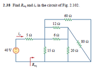
Transcribed Image Text:2.38 Find Req and i, in the circuit of Fig. 2.102.
60 2
ww
120
-ww
5a
62
-ww
ww
80 2
40 V
15 2
202
Expert Solution
This question has been solved!
Explore an expertly crafted, step-by-step solution for a thorough understanding of key concepts.
This is a popular solution
Trending nowThis is a popular solution!
Step by stepSolved in 2 steps with 2 images

Knowledge Booster
Similar questions
- In a series circuit, certain general rules may be stated with regard to quantities of voltage, current, resistance, and power. Express these rules, using your own words: "In a series circuit, voltage..." "In a series circuit, current..." "In a series circuit, resistance..." "In a series circuit, power..." For each of these rules, explain why it is true.arrow_forwardSupply AC = 24Vp (peak) at 60Hz Diodes = Silicon Load Resistance = 1000 ohmsarrow_forwardPRELIMINARY EXERCISE Important Note: You are required to do this exercise BEFORE the lab session. a. Explain what is loading effect in measurement. b. Draw the connection using the potentionmeter shown in Figure(i) as a voltage divider. c. The resistance value in Figure (i) are R₁ = 5 k2, R₂-5 k2 and R, -5 k2 respectively. Calculate the error of Moving Coil Meter if it has internal resistance 10 k2 and voltage supply (Vs) is 10V. m Figure (i) d. Discuss the error in voltage measurement between low and high resistance circuit. e. Briefly discuss the difference between a logarithnm and linear track. f. Explain the input and output impedance of buffer circuit. What are the functions of buffer in instrumentation and measurement.arrow_forward
- Which of the following statements are correct for the circuit below? Thanks to the capacitors I – C1 and C2, the voltage gain of the circuit increases. II – Capacitors C1 and C2 are coupling capacitors and provide an isolation function between AC and DC voltages in the circuit. Thanks to the III – RE resistor, the voltage gain of the circuit increases. Thanks to the IV – RE resistor, the stability of the circuit increases. The V – C3 Capacitor is a bypass capacitor and prevents the loss of voltage gain. Capacitor VI – C3 is a coupling capacitor and has no effect on the voltage gain in the circuit. VII – As the value of the source internal resistance Rs increases, the voltage gain decreases. VIII – The voltage gain decreases as the value of any RL load to be added to the circuit increasesarrow_forwardDetermine the total resistance and total current, as well as the current, voltage and power that exists in each of the resistances of the following resistive mixed type circuitarrow_forwardThe electrical devices can be connected either in the way of series circuit or parallel circuit. Illustrate an example of each circuit, explain the effects of the circuit orientation on the current, voltage, and resistance.arrow_forward
- For circuit given in Figure 3 use Complete Diode Model and find the voltage across R1 and R2 and total current flowing in this circuit. Given that diode forward resistance is 15 Ohms for D1 and 10 Ohms for D2, also reverse current flowing acrossD2 is 20 micro Amperes. DI Ri 50 2 ww D2 Re100 오 www 10 V R3150 2arrow_forward1- spark gaps testing method is applicable for testing 2- the electrical circuit that we use to measure high voltages and is not affected by frequency change 3- We can say high voltages if exceed ------------ V (Alternating voltages) 4- Transient voltages which are caused over voltages be in two forms 5- High voltages can be generated for testing in three ways ------arrow_forwardAn example of Simple Resistive Circuits is ,arrow_forward
- Subject:Circuits INote:Support the problems with circuit diagram and label the pertinent partsPlease with full solutionarrow_forwardFind out the IT and RT for the given circuit: Attach simulation screenshot.arrow_forwardQ1// Analysis the circuit shown in figure below. SET J2 Q2 CLK K2 RESET SET J1 Q1 CLK K1 RESET CLK •arrow_forward
arrow_back_ios
SEE MORE QUESTIONS
arrow_forward_ios
Recommended textbooks for you
 Introductory Circuit Analysis (13th Edition)Electrical EngineeringISBN:9780133923605Author:Robert L. BoylestadPublisher:PEARSON
 Delmar's Standard Textbook Of ElectricityElectrical EngineeringISBN:9781337900348Author:Stephen L. HermanPublisher:Cengage Learning
 Programmable Logic ControllersElectrical EngineeringISBN:9780073373843Author:Frank D. PetruzellaPublisher:McGraw-Hill Education
 Fundamentals of Electric CircuitsElectrical EngineeringISBN:9780078028229Author:Charles K Alexander, Matthew SadikuPublisher:McGraw-Hill Education
 Electric Circuits. (11th Edition)Electrical EngineeringISBN:9780134746968Author:James W. Nilsson, Susan RiedelPublisher:PEARSON
 Engineering ElectromagneticsElectrical EngineeringISBN:9780078028151Author:Hayt, William H. (william Hart), Jr, BUCK, John A.Publisher:Mcgraw-hill Education,

Introductory Circuit Analysis (13th Edition)
Electrical Engineering
ISBN:9780133923605
Author:Robert L. Boylestad
Publisher:PEARSON

Delmar's Standard Textbook Of Electricity
Electrical Engineering
ISBN:9781337900348
Author:Stephen L. Herman
Publisher:Cengage Learning

Programmable Logic Controllers
Electrical Engineering
ISBN:9780073373843
Author:Frank D. Petruzella
Publisher:McGraw-Hill Education

Fundamentals of Electric Circuits
Electrical Engineering
ISBN:9780078028229
Author:Charles K Alexander, Matthew Sadiku
Publisher:McGraw-Hill Education

Electric Circuits. (11th Edition)
Electrical Engineering
ISBN:9780134746968
Author:James W. Nilsson, Susan Riedel
Publisher:PEARSON

Engineering Electromagnetics
Electrical Engineering
ISBN:9780078028151
Author:Hayt, William H. (william Hart), Jr, BUCK, John A.
Publisher:Mcgraw-hill Education,