
Elements Of Electromagnetics
7th Edition
ISBN: 9780190698614
Author: Sadiku, Matthew N. O.
Publisher: Oxford University Press
expand_more
expand_more
format_list_bulleted
Related questions
Question
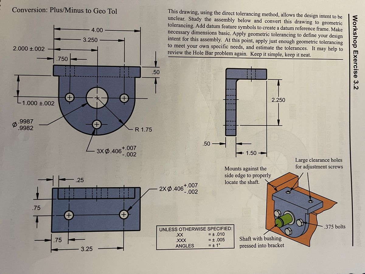
This drawing using the direct tolerancing method, allows the design intent to be unclear. Study the assembly below and convert this drawing to geometric tolerancing. Add datum feature symbols to create a datum reference frame. Make necessary dimensions basic. Apply geometric tolerancing to define your design intent for this assembly. At this point, apply just enough geometric tolderancing to meet your own specific needs, and estimate the tolerances.
Please help!! Also please refer to the attached image.

Transcribed Image Text:Conversion: Plus/Minus to Geo Tol
This drawing, using the direct tolerancing method, allows the design intent to be
unclear. Study the assembly below and convert this drawing to geometric
tolerancing. Add datum feature symbols to create a datum reference frame. Make
necessary dimensions basic. Apply geometric tolerancing to define your design
intent for this assembly. At this point, apply just enough geometric tolerancing
to meet your own specific needs, and estimate the tolerances. It may help to
review the Hole Bar problem again. Keep it simple, keep it neat.
4.00
3.250
2.000 ±.002
.750
.50
2.250
1.000 +.002
.9987
.9982
R 1.75
.50 -
+.007
3XФ.406
1.50 +
-.002
Large clearance holes
for adjustment screws
Mounts against the
side edge to properly
.25
locate the shaft.
+.007
2X Ф 406002
.75
.375 bolts
UNLESS OTHERWISE SPECIFIED:
= ± .010
.XX
.75
.XXX
= ±.005
Shaft with bushing
ANGLES
= ± 1°
pressed into bracket
-3.25
Workshop Exercise 3.2
Expert Solution
This question has been solved!
Explore an expertly crafted, step-by-step solution for a thorough understanding of key concepts.

This is a popular solution

Trending nowThis is a popular solution!

Step by stepSolved in 3 steps with 3 images

Knowledge Booster

Similar questions
- Hello Sir,Good Evening. I have a question in my homework realated geometry tolerance lesson. The following below is my question. Please advice thank you. "What is the difference between position tolerance and orientation tolerance?"arrow_forwardThe entire top surface on the part below must be flat within 0.5 but each 25x25 patch must be flat within 0.1. Apply the necessary geometric controls to achieve this result. Please refer to the attached image.arrow_forwardhow do I dimension the object shown below assume grid spacing is 0.2arrow_forward
- Hello pls sketch left side, front and top viewsarrow_forwardHello Sir.Good Night. I have a question in my homework related geometry tolerance lesson. The following below is my question. Please advice. Thank youarrow_forwardI need a clear answer by hand, not by keyboard and fast answer within 20 minutes. Thank you | dybalaarrow_forward
- Can someone please help me to solve this graphically on CAD as well as analytically. Show all work thank you!arrow_forwardPlease help. I need help with all 4 questions. Apply geometric tolerancing to part according to the instructions below. This exercise will provide you with experience in correctly applying and interpreting geometric tolerancing symbology. If you have trouble applying the symbols, page through this unit looking for similar examples. The Hole Bar in this unit is a good reference. Draw symbols and feature control frames clearly and neatly. 1. Establish all necessary basic dimensions. 2. Position the .250 hole within a diameter of .005 RFS relative to datum features A,B,C. 3. Position the three holes within a diamter of .012 at MMC relative to datum features A,B,C. 4. In the front view, identify the upper right corner as point "Y" and the lower left corner as point "X". Apply a profile tolerance of .020 between points X and Y relative to datum features A,B,C. Please refer to the attached image.arrow_forwardUsing AutoCAD, draw the following image using object snap modes step by steparrow_forward
arrow_back_ios
arrow_forward_ios
Recommended textbooks for you
- Elements Of ElectromagneticsMechanical EngineeringISBN:9780190698614Author:Sadiku, Matthew N. O.Publisher:Oxford University Press
 Mechanics of Materials (10th Edition)Mechanical EngineeringISBN:9780134319650Author:Russell C. HibbelerPublisher:PEARSON
 Thermodynamics: An Engineering ApproachMechanical EngineeringISBN:9781259822674Author:Yunus A. Cengel Dr., Michael A. BolesPublisher:McGraw-Hill Education
  Control Systems EngineeringMechanical EngineeringISBN:9781118170519Author:Norman S. NisePublisher:WILEY
 Mechanics of Materials (MindTap Course List)Mechanical EngineeringISBN:9781337093347Author:Barry J. Goodno, James M. GerePublisher:Cengage Learning
 Engineering Mechanics: StaticsMechanical EngineeringISBN:9781118807330Author:James L. Meriam, L. G. Kraige, J. N. BoltonPublisher:WILEY
Elements Of Electromagnetics
Mechanical Engineering
ISBN:9780190698614
Author:Sadiku, Matthew N. O.
Publisher:Oxford University Press
Mechanics of Materials (10th Edition)
Mechanical Engineering
ISBN:9780134319650
Author:Russell C. Hibbeler
Publisher:PEARSON
Thermodynamics: An Engineering Approach
Mechanical Engineering
ISBN:9781259822674
Author:Yunus A. Cengel Dr., Michael A. Boles
Publisher:McGraw-Hill Education
Control Systems Engineering
Mechanical Engineering
ISBN:9781118170519
Author:Norman S. Nise
Publisher:WILEY
Mechanics of Materials (MindTap Course List)
Mechanical Engineering
ISBN:9781337093347
Author:Barry J. Goodno, James M. Gere
Publisher:Cengage Learning
Engineering Mechanics: Statics
Mechanical Engineering
ISBN:9781118807330
Author:James L. Meriam, L. G. Kraige, J. N. Bolton
Publisher:WILEY