Elements Of Electromagnetics
7th Edition
ISBN: 9780190698614
Author: Sadiku, Matthew N. O.
Publisher: Oxford University Press
expand_more
expand_more
format_list_bulleted
Question
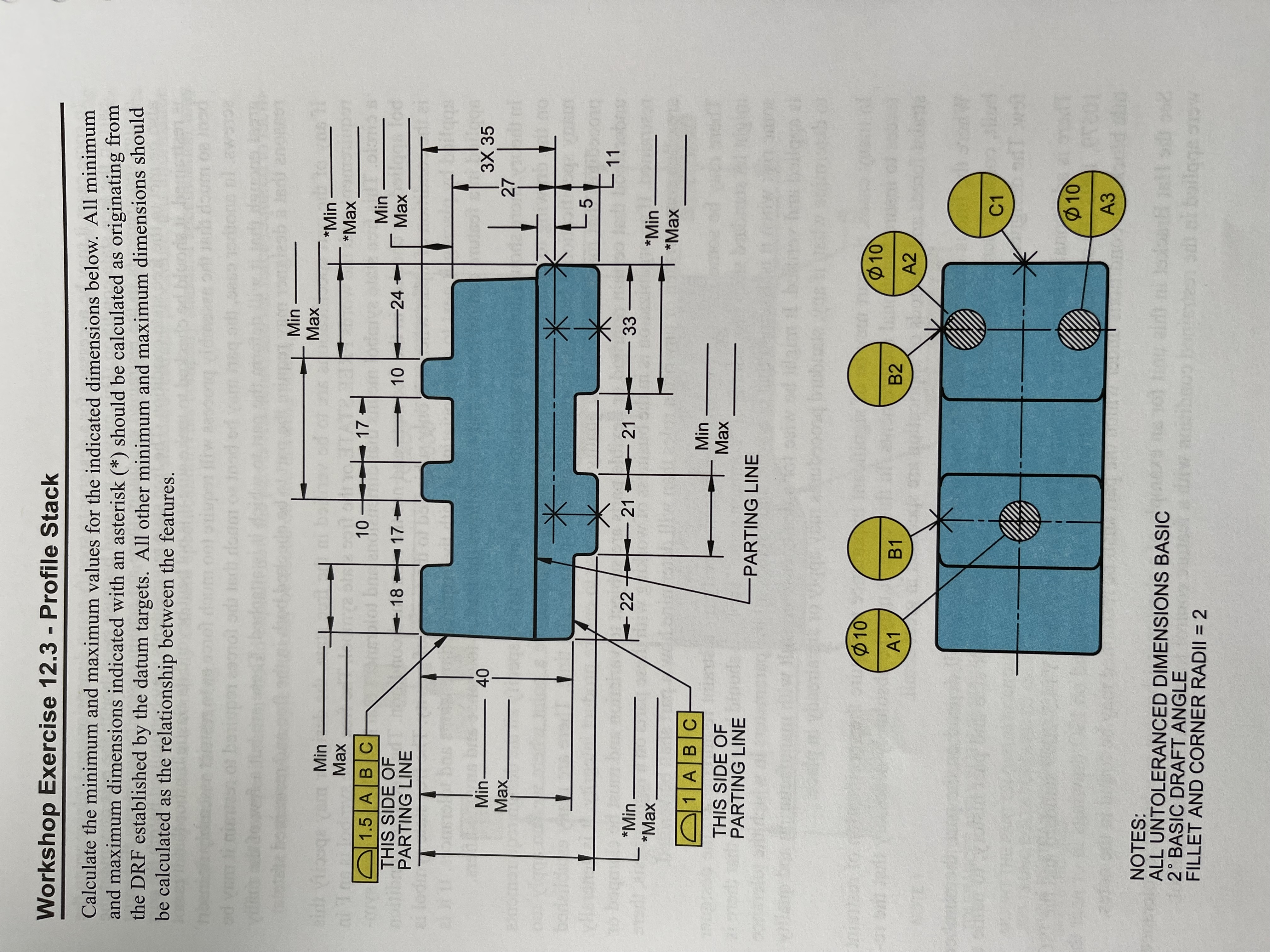
Calculate the minimum and maximum values for the indicated dimensions attached. All minimum and maximum dimensions indicated with an asterick (*) should be calculated as originating from the DRF established by the datum targets. All other minimum and maximum dimensions should be calculated as the relationship between the features.
Please refer to attached image.

Transcribed Image Text:**Workshop Exercise 12.3 - Profile Stack**
Calculate the minimum and maximum values for the indicated dimensions below. All minimum and maximum dimensions indicated with an asterisk (*) should be calculated as originating from the Datum Reference Frame (DRF) established by the datum targets. Other minimum and maximum dimensions should be calculated as the relationship between the features.
**Diagram Explanation:**
The diagram features a complex shaped component with specific dimensions and datum points highlighted.
- **Part Annotations and Dimensions:**
- The component is divided by a parting line.
- Two datum targets are specified: this side of the parting line (1.5 A B C and 1 A B C).
- Various feature dimensions are given, with certain dimensions marked as "Min" or "Max" indicating variability in those measurements.
- Dimensions include:
- Vertical: 40 units from the top to the base.
- Horizontal sections with steps: 17, 17, 10, 24 units respectively.
- Vertical edge sections with specific heights: 18, 27, 27, 5 units.
- Angled section with specified height: 3 by 35 units.
- Feature diameter: \(\varnothing10\).
- **Datum Features and Points:**
- Several datum points (A1, A2, A3, B1, B2, C1) are represented by yellow circles with positions on the component.
- Datum targets are used to establish references for other measurements on the object.
**Notes Section:**
- All untoleranced dimensions are considered basic.
- There is a 2° basic draft angle for the part.
- A consistent fillet and corner radii of 2 is assumed across features.
This exercise involves calculating the variability of dimensions from the established datum features, emphasizing precision in manufacturing and design processes.
Expert Solution
This question has been solved!
Explore an expertly crafted, step-by-step solution for a thorough understanding of key concepts.
Step by stepSolved in 2 steps with 3 images

Knowledge Booster
Learn more about
Need a deep-dive on the concept behind this application? Look no further. Learn more about this topic, mechanical-engineering and related others by exploring similar questions and additional content below.Similar questions
arrow_back_ios
arrow_forward_ios
Recommended textbooks for you
 Elements Of ElectromagneticsMechanical EngineeringISBN:9780190698614Author:Sadiku, Matthew N. O.Publisher:Oxford University Press
 Mechanics of Materials (10th Edition)Mechanical EngineeringISBN:9780134319650Author:Russell C. HibbelerPublisher:PEARSON
 Thermodynamics: An Engineering ApproachMechanical EngineeringISBN:9781259822674Author:Yunus A. Cengel Dr., Michael A. BolesPublisher:McGraw-Hill Education
 Control Systems EngineeringMechanical EngineeringISBN:9781118170519Author:Norman S. NisePublisher:WILEY
 Mechanics of Materials (MindTap Course List)Mechanical EngineeringISBN:9781337093347Author:Barry J. Goodno, James M. GerePublisher:Cengage Learning
 Engineering Mechanics: StaticsMechanical EngineeringISBN:9781118807330Author:James L. Meriam, L. G. Kraige, J. N. BoltonPublisher:WILEY

Elements Of Electromagnetics
Mechanical Engineering
ISBN:9780190698614
Author:Sadiku, Matthew N. O.
Publisher:Oxford University Press

Mechanics of Materials (10th Edition)
Mechanical Engineering
ISBN:9780134319650
Author:Russell C. Hibbeler
Publisher:PEARSON

Thermodynamics: An Engineering Approach
Mechanical Engineering
ISBN:9781259822674
Author:Yunus A. Cengel Dr., Michael A. Boles
Publisher:McGraw-Hill Education

Control Systems Engineering
Mechanical Engineering
ISBN:9781118170519
Author:Norman S. Nise
Publisher:WILEY

Mechanics of Materials (MindTap Course List)
Mechanical Engineering
ISBN:9781337093347
Author:Barry J. Goodno, James M. Gere
Publisher:Cengage Learning

Engineering Mechanics: Statics
Mechanical Engineering
ISBN:9781118807330
Author:James L. Meriam, L. G. Kraige, J. N. Bolton
Publisher:WILEY