
Fundamentals of Geotechnical Engineering (MindTap Course List)
5th Edition
ISBN: 9781305635180
Author: Braja M. Das, Nagaratnam Sivakugan
Publisher: Cengage Learning
expand_more
expand_more
format_list_bulleted
Related questions
Concept explainers
Question
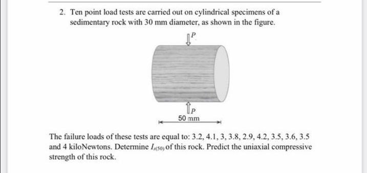

Transcribed Image Text:2. Ten point load tests are carried out on cylindrical specimens of a
sedimentary rock with 30 mm diameter, as shown in the figure.
50 mm
The failure loads of these tests are equal to: 3.2, 4.1, 3, 3.8, 2.9, 4.2, 3.5, 3.6, 3.5
and 4 kiloNewtons. Determine Iyso of this rock. Predict the uniaxial compressive
strength of this rock.
Expert Solution
This question has been solved!
Explore an expertly crafted, step-by-step solution for a thorough understanding of key concepts.

Step by stepSolved in 3 steps with 3 images

Knowledge Booster


Learn more about
Need a deep-dive on the concept behind this application? Look no further. Learn more about this topic, civil-engineering and related others by exploring similar questions and additional content below.Similar questions
- Redo Problem 6.12 using Figure 6.15. 6.12 Refer to Problem 6.1. Using Eqs. (6.3) and (6.29), estimate the average stress increase (av) below the center of the loaded area between depths of 3 m and 6 m. 6.1 A flexible circular area is subjected to a uniformly distributed load of 150 kN/m2 (Figure 6.2). The diameter of the load area is 2 m. Determine the stress increase in a soil mass at points located 3 m below the loaded area at r = 0, 0.4 m, 0.8 m, and 1 m. Use Boussinesqs solution. Figure 6.2 Increase in pressure under a uniformly loaded flexible circular areaarrow_forwardRefer to Problem 6.1. Using Eqs. (6.3) and (6.29), estimate the average stress increase (Δσav) below the center of the loaded area between depths of 3 m and 6 m. 6.1 A flexible circular area is subjected to a uniformly distributed load of 150kN/m2 (Figure 6.2). The diameter of the load area is 2 m. Determine the stress increase in a soil mass at points located 3 m below the loaded area at r = 0. 0.4 m, 0.8 m, and 1 m. Use Boussinesq’s solution. Figure 6.2 Increase in pressure under a uniformly loaded flexible circular areaarrow_forwardFor the same line loads given in Problem 10.8, determine the vertical stress increase, z, at a point located 4 m below the line load, q2. Refer to Figure 10.41. Determine the vertical stress increase, z, at point A with the following values: q1 = 110 kN/m, q2 = 440 kN/m, x1 = 6 m, x2 = 3 m, and z = 4 m. Figure 10.41arrow_forward
- Refer to the flexible loaded rectangular area shown in Figure 10.47. Using Eq. (10.36), determine the vertical stress increase below the center of the loaded area at depths z = 3, 6, 9, 12, and 15 m. Figure 10.47arrow_forwardUse Eq. (6.14) to determine the stress increase () at z = 10 ft below the center of the area described in Problem 6.5. 6.5 Refer to Figure 6.6, which shows a flexible rectangular area. Given: B1 = 4 ft, B2 = 6 ft, L1, = 8 ft, and L2 = 10 ft. If the area is subjected to a uniform load of 3000 lb/ft2, determine the stress increase at a depth of 10 ft located immediately below point O. Figure 6.6 Stress below any point of a loaded flexible rectangular areaarrow_forwardA 300 mm 450 mm plate was used in carrying out a plate loading test in a sand, during which the plate settled 5 mm under the applied pressure of 250 kN/m2. a. What is the coefficient of subgrade reaction for a 300 mm wide square plate? b. What would be the coefficient of subgrade reaction of a 2 m 3 m foundation?arrow_forward
- Repeat Problem 10.12 for q = 700 kN/m2, B = 8 m, and z = 4 m. In this case, point A is located below the centerline under the strip load. 10.12 Refer to Figure 10.43. A strip load of q = 1450 lb/ft2 is applied over a width with B = 48 ft. Determine the increase in vertical stress at point A located z = 21 ft below the surface. Given x = 28.8 ft. Figure 10.43arrow_forwardA point load of 1000 kN is applied at the ground level. Plot the variation of the vertical stress increase z with depth at horizontal distances of 1 m, 2 m, and 4 m from the load.arrow_forwardThe soil profile at a site consists of 10 m of gravelly sand underlain by a soft clay layer. The water table lies 1 m below the ground level. The moist and saturated unit weights of the gravelly sand are 17.0 kN/m3 and 20.0 kN/m3, respectively. Due to some ongoing construction work, it is proposed to lower the water table to 3 m below the ground level. What will be the change in the effective stress on top of the soft clay layer?arrow_forward
arrow_back_ios
arrow_forward_ios
Recommended textbooks for you
- Fundamentals of Geotechnical Engineering (MindTap...Civil EngineeringISBN:9781305635180Author:Braja M. Das, Nagaratnam SivakuganPublisher:Cengage Learning
 Principles of Foundation Engineering (MindTap Cou...Civil EngineeringISBN:9781305081550Author:Braja M. DasPublisher:Cengage Learning
 Principles of Geotechnical Engineering (MindTap C...Civil EngineeringISBN:9781305970939Author:Braja M. Das, Khaled SobhanPublisher:Cengage Learning
  Principles of Foundation Engineering (MindTap Cou...Civil EngineeringISBN:9781337705028Author:Braja M. Das, Nagaratnam SivakuganPublisher:Cengage Learning
Fundamentals of Geotechnical Engineering (MindTap...
Civil Engineering
ISBN:9781305635180
Author:Braja M. Das, Nagaratnam Sivakugan
Publisher:Cengage Learning
Principles of Foundation Engineering (MindTap Cou...
Civil Engineering
ISBN:9781305081550
Author:Braja M. Das
Publisher:Cengage Learning
Principles of Geotechnical Engineering (MindTap C...
Civil Engineering
ISBN:9781305970939
Author:Braja M. Das, Khaled Sobhan
Publisher:Cengage Learning
Principles of Foundation Engineering (MindTap Cou...
Civil Engineering
ISBN:9781337705028
Author:Braja M. Das, Nagaratnam Sivakugan
Publisher:Cengage Learning