
Introductory Circuit Analysis (13th Edition)
13th Edition
ISBN: 9780133923605
Author: Robert L. Boylestad
Publisher: PEARSON
expand_more
expand_more
format_list_bulleted
Related questions
Question
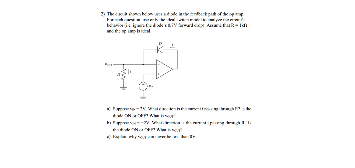

Transcribed Image Text:### Circuit Analysis with Diode in Feedback Path
**Problem Statement:**
The circuit shown uses a diode in the feedback path of an operational amplifier (op amp). For analysis, use the ideal switch model to understand the circuit’s behavior, ignoring the diode’s 0.7V forward drop. Assume:
- **Resistor (R):** 1kΩ
- The op amp is ideal.
**Circuit Diagram Explanation:**
The circuit features:
- An op amp with an inverting input connected to the input voltage \( V_{\text{IN}} \).
- A feedback loop with a diode (D) and a resistor (R) connected in series.
- The non-inverting input is grounded.
**Questions:**
a) **Given \( V_{\text{IN}} = 2V \):**
- Determine the current direction \( i \) through R.
- Is the diode ON or OFF?
- What is the output voltage \( V_{\text{OUT}} \)?
b) **Given \( V_{\text{IN}} = -2V \):**
- Determine the current direction \( i \) through R.
- Is the diode ON or OFF?
- What is the output voltage \( V_{\text{OUT}} \)?
c) **Explain why \( V_{\text{OUT}} \) can never be less than 0V.**
**Guidelines for Solution:**
- Use the behavior of the ideal diode: Conducts when forward-biased (ON), blocks when reverse-biased (OFF).
- The ideal op amp ensures the voltage at both inputs is equal in steady state.
**Graphical Explanation:**
The schematic shows:
- **Diode (D):** Controls feedback current, turning ON or OFF based on \( V_{\text{IN}} \).
- **Resistor (R):** 1kΩ defines current \( i \) when the diode is conducting.
- **Op Amp Configuration:** Inverting setup with diode feedback controlling \( V_{\text{OUT}} \).
**Theoretical Understanding:**
- For positive \( V_{\text{IN}} \): Diode likely conducts, impacting \( V_{\text{OUT}} \).
- For negative \( V_{\text{IN}} \): Diode likely blocks, suggesting \( V_{\text{OUT}} \) is 0V.
- Positive feedback behavior ensures \( V_{\text{OUT}} \) remains non-negative.
Expert Solution
This question has been solved!
Explore an expertly crafted, step-by-step solution for a thorough understanding of key concepts.

This is a popular solution

Trending nowThis is a popular solution!

Step by stepSolved in 3 steps with 3 images

Knowledge Booster


Learn more about
Need a deep-dive on the concept behind this application? Look no further. Learn more about this topic, electrical-engineering and related others by exploring similar questions and additional content below.Similar questions
- Figure 3 shows a Hartley oscillator. Assume that the op-amp employed in the figure is an ideal op-amp, and R1= 20 kΩ, R2 = 60 kΩ, L1=10 mH. b) State the Barkhausen criterion for sustained oscillation.c) Explain briefly how the phase shift requirement for sustained oscillation ismet in the circuit of Figure 3.d) The feedback ratio and oscillation frequency of Figure 3 are givenrespectively by, B = -L2/L1 and w0 = 1 / sqrt(L1 +L2)C Determine the values of C and L2 in order for the circuit to oscillate at a frequency of 200 Hz.arrow_forwardIf in the oscillator block diagram shown in Figure, = 0.1V, A = 100 and m = 0.01, then the circuit will. V₁ mVo Voltage Gain A Feedback Circuit Varrow_forwardThe midrange open-loop gain, "Aol(mid)" of a certain op-amp is 80,000. If the open-loop critical frequency is 1 kHz, what is the open-loop gain, "Aol" at each of the following frequencies? (a)100 Hz (b) 1 MHzarrow_forward
- Operational Amplifier (Op-Amp) is a solid-state device with voltage amplification capabilities as shown in Figure Q1. (a) Name the function of Op-Amp U1, U2 and U3 in Figure Q1. (b) Derive the output voltage (Vol, Voz and Vo3) of each Op-Amp in Figure Q1. Based on derivation in Q1(b), calculate the output voltages (Vol, Vo2 and Vo3) of the circuit. All the Op-Amps are powered with + 12V voltage supplies. Given: Ra = Rb = 1 kN, Ry = Rx = 10 kN, Ra = 3.6 kN, Rr = 3 k2. The input voltages: V,= V = 5 V. (c) (d) Draw and label clearly the sinusoidal output of Vo1, Vo2 and Vo3.arrow_forwardplease do question 2 and 3arrow_forwardAnswer the following questions a) What assumption do we make for an ideal op - amp? b) Explain what slew rate is why it is important characteristic for an op amp.arrow_forward
arrow_back_ios
arrow_forward_ios
Recommended textbooks for you
- Introductory Circuit Analysis (13th Edition)Electrical EngineeringISBN:9780133923605Author:Robert L. BoylestadPublisher:PEARSON
 Delmar's Standard Textbook Of ElectricityElectrical EngineeringISBN:9781337900348Author:Stephen L. HermanPublisher:Cengage Learning
 Programmable Logic ControllersElectrical EngineeringISBN:9780073373843Author:Frank D. PetruzellaPublisher:McGraw-Hill Education
  Fundamentals of Electric CircuitsElectrical EngineeringISBN:9780078028229Author:Charles K Alexander, Matthew SadikuPublisher:McGraw-Hill Education
 Electric Circuits. (11th Edition)Electrical EngineeringISBN:9780134746968Author:James W. Nilsson, Susan RiedelPublisher:PEARSON
 Engineering ElectromagneticsElectrical EngineeringISBN:9780078028151Author:Hayt, William H. (william Hart), Jr, BUCK, John A.Publisher:Mcgraw-hill Education,
Introductory Circuit Analysis (13th Edition)
Electrical Engineering
ISBN:9780133923605
Author:Robert L. Boylestad
Publisher:PEARSON
Delmar's Standard Textbook Of Electricity
Electrical Engineering
ISBN:9781337900348
Author:Stephen L. Herman
Publisher:Cengage Learning
Programmable Logic Controllers
Electrical Engineering
ISBN:9780073373843
Author:Frank D. Petruzella
Publisher:McGraw-Hill Education
Fundamentals of Electric Circuits
Electrical Engineering
ISBN:9780078028229
Author:Charles K Alexander, Matthew Sadiku
Publisher:McGraw-Hill Education
Electric Circuits. (11th Edition)
Electrical Engineering
ISBN:9780134746968
Author:James W. Nilsson, Susan Riedel
Publisher:PEARSON
Engineering Electromagnetics
Electrical Engineering
ISBN:9780078028151
Author:Hayt, William H. (william Hart), Jr, BUCK, John A.
Publisher:Mcgraw-hill Education,