Introductory Circuit Analysis (13th Edition)
13th Edition
ISBN: 9780133923605
Author: Robert L. Boylestad
Publisher: PEARSON
expand_more
expand_more
format_list_bulleted
Concept explainers
Question
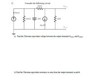
Please answer (a) and (b)

Transcribed Image Text:2)
Consider the following circuit:
15kN
Vout,a
10mA
10k2
30V
3mA
Vaut
a) Find the Thévenin equivalent voltage between the output terminals Vout,a and V out,b-
b) Find the Thévenin equivalent resistance as seen from the output terminals a and b.
Expert Solution
This question has been solved!
Explore an expertly crafted, step-by-step solution for a thorough understanding of key concepts.
Step by stepSolved in 3 steps with 3 images

Knowledge Booster
Learn more about
Need a deep-dive on the concept behind this application? Look no further. Learn more about this topic, electrical-engineering and related others by exploring similar questions and additional content below.Similar questions
- Find the input resistance between terminals B and G in the circuit shown in the figure. The voltage vx is a test voltage with the input resistance Rin defined as Rin = vx / ix.arrow_forward3-2) Draw the circuit diagram to output F given in the expression above by referring to schematics for 2-2) and 2-3). Use the space below to draw both the IC with pin assignments and a circuit F schematic. Schematic diagram: IC diagram: +3V IND Cate che GNDarrow_forwardFigure shows a transistor switching circuit. Find the Vcc and Rc, which causes the output voltage to have a peak to peak value of 6V (given that the input voltage signal Vi, and the output voltage signal Vo, have units of Volt) Fone: V₁ 10k2 www +Vcc Rc V₂ B-100arrow_forward
- Negative Clamping Circuit: Can you explain why the output voltage gets shifted down logically?arrow_forwardDraw the circuit for the following output. Show your complete analysis. E1 = 10V, E2 = 6Varrow_forward16 In figure H below Find Vth 17. In figure H below Find Rth 18. In figure H find Maximum Power Transfer at RL +24 V H. 100 15 0 RL 150 www 20 0arrow_forward
- For the circuit below with input voltage V1 shown and the initial voltage across Cl equal zero, find the transient response voltage across the resistor R1 and plot the results: (Provide your calculations and reasoning for your answer.) C1 5u V1- 15 V2 -5 TD = 0.010 TR = 0.00001 TF = 0.00001 PW.1 PER = V1 R1 1k Input Voltage V1 20 15 10 -0.02 -0.01 0.01 0.02 0.03 0.04 0.05 0.06 Time (sec) (A) TAarrow_forwardReset WED W=O W =l EhD DII W=0 Derive the following state-table Present state Next state output z2zlz0 W=0 W=1 A 000 B 001 C 010 D 011 E 100arrow_forwardI need to design a power supply 110v , with an output between 6 and 9v. I did a design and I implemented a resistor after the bridge as a surge protector for the diode. I need to know if this is the right design and I need some calculations for the elements to provide an output between 6 and 9v.arrow_forward
arrow_back_ios
SEE MORE QUESTIONS
arrow_forward_ios
Recommended textbooks for you
 Introductory Circuit Analysis (13th Edition)Electrical EngineeringISBN:9780133923605Author:Robert L. BoylestadPublisher:PEARSON
 Delmar's Standard Textbook Of ElectricityElectrical EngineeringISBN:9781337900348Author:Stephen L. HermanPublisher:Cengage Learning
 Programmable Logic ControllersElectrical EngineeringISBN:9780073373843Author:Frank D. PetruzellaPublisher:McGraw-Hill Education
 Fundamentals of Electric CircuitsElectrical EngineeringISBN:9780078028229Author:Charles K Alexander, Matthew SadikuPublisher:McGraw-Hill Education
 Electric Circuits. (11th Edition)Electrical EngineeringISBN:9780134746968Author:James W. Nilsson, Susan RiedelPublisher:PEARSON
 Engineering ElectromagneticsElectrical EngineeringISBN:9780078028151Author:Hayt, William H. (william Hart), Jr, BUCK, John A.Publisher:Mcgraw-hill Education,

Introductory Circuit Analysis (13th Edition)
Electrical Engineering
ISBN:9780133923605
Author:Robert L. Boylestad
Publisher:PEARSON

Delmar's Standard Textbook Of Electricity
Electrical Engineering
ISBN:9781337900348
Author:Stephen L. Herman
Publisher:Cengage Learning

Programmable Logic Controllers
Electrical Engineering
ISBN:9780073373843
Author:Frank D. Petruzella
Publisher:McGraw-Hill Education

Fundamentals of Electric Circuits
Electrical Engineering
ISBN:9780078028229
Author:Charles K Alexander, Matthew Sadiku
Publisher:McGraw-Hill Education

Electric Circuits. (11th Edition)
Electrical Engineering
ISBN:9780134746968
Author:James W. Nilsson, Susan Riedel
Publisher:PEARSON

Engineering Electromagnetics
Electrical Engineering
ISBN:9780078028151
Author:Hayt, William H. (william Hart), Jr, BUCK, John A.
Publisher:Mcgraw-hill Education,