Structural Analysis
6th Edition
ISBN: 9781337630931
Author: KASSIMALI, Aslam.
Publisher: Cengage,
expand_more
expand_more
format_list_bulleted
Concept explainers
Question
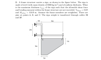
A frame structure carries a sign, as shown in the figure below. The sign ismade of steel (with mass density of 8000 kg/m3) and of uniform thickness. What is the maximum thickness t_max of the sign such that the allowable shear forceand bending moment within the frame structure are not exceeded: Vallow= 8 kN and Mallow= 12 kN·m. Assume the frame members are weightless. There are pins at points A ,B, andC. The sign weight is transferred through cables CE and DF.

Transcribed Image Text:2 - A frame structure carries a sign, as shown in the figure below. The sign is
made of steel (with mass density of 8000 kg/m³) and of uniform thickness. What
is the maximum thickness tmax of the sign such that the allowable shear force
and bending moment within the frame structure are not exceeded: Vallow = 8 kN
and Mallow
pins at points A, B, and C. The sign weight is transferred through cables CE
12 kN-m. Assume the frame members are weightless. There are
and DF.
1m
+
4m
А
2m
|C
E
F
1m
3m
1m
B.
Expert Solution
arrow_forward
Step 1

arrow_forward
Step 2

Step by stepSolved in 3 steps with 3 images

Knowledge Booster
Learn more about
Need a deep-dive on the concept behind this application? Look no further. Learn more about this topic, civil-engineering and related others by exploring similar questions and additional content below.Similar questions
- A rigid bar GH of length L is supported by a hinge and a spring of stiffness K as shown in the figure below. The buckling load, Por, for the bar will be P K HOWN Larrow_forward14. A pin-connected structure consists of a rigid beam ABCD and two supporting bars. Bar (1) is an aluminum alloy [E = 70 GPa] with a cross-sectional area of A₁ = 2,400 mm². Bar (2) is a bronze alloy [E = 100 GPa] with a cross-sectional area of A2 = 6,000 mm². All bars are unstressed before the load P is applied. If a load of P = 535 kN is applied at B, determine the normal force in bar (1). A) B) D) E) 2.9 m 0.8 m 391 kN 325 kN 301 kN 247 kN 181 kN B 1.5 m P = 535 KN (2) C 3.3 m 1.2 m F₁ K 0.8m D + 535 1.2marrow_forwardThe force in DB of the truss shown in below figure is W A 200 5 W tension O VW tension 5m 2 W compression √3 W compression E D 2W 5m B Warrow_forward
- Pin-connected rigid bars AB, BC, and CD are initially held in the positions shown by taut wires (1) and (2). The bar lengths are a = 36 ft and b = 27 ft. Joint Cis given a horizontal displacement of 5.7 in. to the right. (Note that this displacement causes both joints B and C to move to the right and slightly downward.) What is the change in the average normal strain in wire (1) after the displacement? B (1), a (2) Answer: = i (0)arrow_forwardThe initial compressive force of a steel column can be determined by Euler's buckling formula. The column has the following properties: A = 9484 mm² Fy=345 MPa x = 164 x 106 mm4 ly = 23 x 106 mm4 Proportional limit, fs = 290 MPa The x-axis has an unbraced length of 10 m which is pinned at the top and fixed at the bottom with an k = 0.70. The y-axis has unbraced length of 5 m due to the bracing at the mid-height. Compute the initial compressive load of the column. Select the correct response: 6606.59 KN 3706.14 KN E = 200 GPa 1816.01 kN 926.53 kNarrow_forwardFigure below shows a uniformly tapering bar of rectangular cross-section of length L and thickness t. The width of the bar at one end is b₁ and the width at the other end is b2, where (b₂> b₁). The bar is subjected to an axial force P. The axial deformation due to load P is given by _mm. b₂ PL atE b₁ = 20 mm b₂-40 mm -In () then the value of (a + c) isarrow_forward
- I need help with this exercise from my homework. I have no idea about how to solve it. I need an step by step solving and explanation, please.arrow_forwardThe force in DB of the truss shown in below figure is W A C O VW tension 5m √3 W compression 2 W compression 5 W tension E D 2W 5m Barrow_forwardDerive the relationship among Unit weight, Porosity and moisture content. - Consider a soil that has a total volume equal to 1. Expressed the weight of soil solids, dry unit weight, moist unit weight - Clue use the formula of porosity to start V₂ V n=arrow_forward
- The plate has a thickness of 20 mm and the force P = 5 kN acts along the centerline of this thickness such that d = 150 mm. (Figure 1) Figure d‡ 200 mm a 1 of 1arrow_forwardExperts Pleae help ASAParrow_forwarda. The beam weighs 3600N. Draw the V and M diagram. b. Assume we do not know the weight of the beam the solid steel bar has a square cross section of side b and is supported as shown. We know that density of steel is 7860 kg/m, calculate the dimension b for which the maximum normal stress due to bending is 50 MPa. C D I-KE -1.2 m-1.2 m 1.2 m Barrow_forward
arrow_back_ios
arrow_forward_ios
Recommended textbooks for you

 Structural Analysis (10th Edition)Civil EngineeringISBN:9780134610672Author:Russell C. HibbelerPublisher:PEARSON
 Principles of Foundation Engineering (MindTap Cou...Civil EngineeringISBN:9781337705028Author:Braja M. Das, Nagaratnam SivakuganPublisher:Cengage Learning
 Fundamentals of Structural AnalysisCivil EngineeringISBN:9780073398006Author:Kenneth M. Leet Emeritus, Chia-Ming Uang, Joel LanningPublisher:McGraw-Hill Education
 Traffic and Highway EngineeringCivil EngineeringISBN:9781305156241Author:Garber, Nicholas J.Publisher:Cengage Learning


Structural Analysis (10th Edition)
Civil Engineering
ISBN:9780134610672
Author:Russell C. Hibbeler
Publisher:PEARSON

Principles of Foundation Engineering (MindTap Cou...
Civil Engineering
ISBN:9781337705028
Author:Braja M. Das, Nagaratnam Sivakugan
Publisher:Cengage Learning

Fundamentals of Structural Analysis
Civil Engineering
ISBN:9780073398006
Author:Kenneth M. Leet Emeritus, Chia-Ming Uang, Joel Lanning
Publisher:McGraw-Hill Education


Traffic and Highway Engineering
Civil Engineering
ISBN:9781305156241
Author:Garber, Nicholas J.
Publisher:Cengage Learning