
Elements Of Electromagnetics
7th Edition
ISBN: 9780190698614
Author: Sadiku, Matthew N. O.
Publisher: Oxford University Press
expand_more
expand_more
format_list_bulleted
Related questions
Question
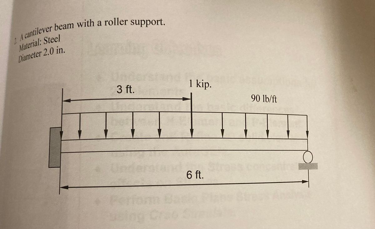
Determine the maximum stress produced by the loads and create the shear and moment diagram for the cantilever beam system.

Transcribed Image Text:2
A cantilever beam with a roller support.
Material: Steel
Diameter 2.0 in.
1 kip.
3 ft.
90 lb/ft
Under
6 ft.
Expert Solution
This question has been solved!
Explore an expertly crafted, step-by-step solution for a thorough understanding of key concepts.

Step by stepSolved in 2 steps with 5 images

Knowledge Booster

Similar questions
- For the beam show below, draw A.F.D, S.F.D, B.M.D 6 kN/m 1 M B. 3 M Marrow_forwardFigure 14.20 Full Alternative Text 14.21 A solid rectangular simply supported timber beam 6 in. wide, 20 in. deep, and 10 ft long carries a concentrated load of 16,000 lb at midspan. Use nominal dimensions. a. Compute the maximum horizontal shear stress at the neutral axis. b. Compute the shear stress 4 in. and 8 in. above and below the neutral axis. Neglect the weight of the beam.arrow_forwardCompute the initial deflection of the beam at midspan under service loads with the following specifications: f'c = 4000 psi, 36-inch height, depth of rebar assumed to be 3 inches less than the height, 16-inch width, 4 #9 bars (tension), Grade 60 rebar, 30' clear spans, service loads of: DL = 0.25k/ft, LL = 1.2k/ft. The DL does NOT include self-weight of the beam or of the precast concrete deck planks that have a weight of 60 PSF. The beam picks up a tributary width of 12 feet. Also, note that this beam is continuous and is the middle beam of 5 equal spans. Check the initial deflections against the ACI deflection requirements. Then calculate the long-term deflections and check those against the ACI requirements. For both situations, assume that finish materials will be attached to the beam. Last: Instead of performing a structural analysis to determine the maximum deflection in the beam, conservatively figure that the maximum deflection will be 60% of what it would have been for a…arrow_forward
- 0.3m 40 KN Icm 5cm 7cm 0,5m 5cm Icm 10 kNm 0.2m Find deflection of the beam at the point where 40kN force is acting and the slope at the supports.arrow_forwardCHAPTER THIR free-body diagrams. chrough 13.47 Refer to the beam shown and draw complete bear and bending monment diagrams. Show ordinates at key points and indicate magnitude of shear and moment. Neglect the beam weight. 8 kips 6 kips 1.5 kips/ft 8'-0" EM 13.39 100 lb 100 lb 300 lb/ft -200 lb/ft B. A.arrow_forwardNote:- • Do not provide handwritten solution. Maintain accuracy and quality in your answer. Take care of plagiarism. • Answer completely. • You will get up vote for sure.arrow_forward
- A 14 ft long simple beam is uniformly loaded with 200 pounds per foot over its entire length. If the beam is 3.625 inches wide and 7.625 inches deep. What is the maximum bending stress? a. 1774 lbf/in² b. 1674 lbf/in² c. 1474 lbf/in² d. 1574 lbf/in²arrow_forwardExercise 38 Section 7.2 (Lesson 14) МeсМovies M9.1 Abeam with a rectangular cross section is simply supported and loaded at its center with a force P. The dimensions b, h, and L are shown in the figure. Given: Find: Determine (a) the maximum bending stress omax and (b) the maximum shear stress in this beam. (c) Then obtain the ratio Tmax/omax: Hint: The maximum stresses T max occur at different locations in the beam. Be sure to show sufficient work to justify your answers. Answers: (a) 3PL/(2bh²), (b) 3P/(4bh), (c) h/(2L)arrow_forwardQ1: For the Concrete Beam shown in Fig. down , Determine For Front Cross Section Area: Ix And lj and K.(radius of Gyration) If the (I; =4.655 mm*) ? Note: Replace each inch in Figure by ((10 mm)). 12 in, 12 in. 3 in. 27 in. in. 3 in. 3 in.arrow_forward
arrow_back_ios
SEE MORE QUESTIONS
arrow_forward_ios
Recommended textbooks for you
- Elements Of ElectromagneticsMechanical EngineeringISBN:9780190698614Author:Sadiku, Matthew N. O.Publisher:Oxford University Press
 Mechanics of Materials (10th Edition)Mechanical EngineeringISBN:9780134319650Author:Russell C. HibbelerPublisher:PEARSON
 Thermodynamics: An Engineering ApproachMechanical EngineeringISBN:9781259822674Author:Yunus A. Cengel Dr., Michael A. BolesPublisher:McGraw-Hill Education
  Control Systems EngineeringMechanical EngineeringISBN:9781118170519Author:Norman S. NisePublisher:WILEY
 Mechanics of Materials (MindTap Course List)Mechanical EngineeringISBN:9781337093347Author:Barry J. Goodno, James M. GerePublisher:Cengage Learning
 Engineering Mechanics: StaticsMechanical EngineeringISBN:9781118807330Author:James L. Meriam, L. G. Kraige, J. N. BoltonPublisher:WILEY
Elements Of Electromagnetics
Mechanical Engineering
ISBN:9780190698614
Author:Sadiku, Matthew N. O.
Publisher:Oxford University Press
Mechanics of Materials (10th Edition)
Mechanical Engineering
ISBN:9780134319650
Author:Russell C. Hibbeler
Publisher:PEARSON
Thermodynamics: An Engineering Approach
Mechanical Engineering
ISBN:9781259822674
Author:Yunus A. Cengel Dr., Michael A. Boles
Publisher:McGraw-Hill Education
Control Systems Engineering
Mechanical Engineering
ISBN:9781118170519
Author:Norman S. Nise
Publisher:WILEY
Mechanics of Materials (MindTap Course List)
Mechanical Engineering
ISBN:9781337093347
Author:Barry J. Goodno, James M. Gere
Publisher:Cengage Learning
Engineering Mechanics: Statics
Mechanical Engineering
ISBN:9781118807330
Author:James L. Meriam, L. G. Kraige, J. N. Bolton
Publisher:WILEY