
Introductory Circuit Analysis (13th Edition)
13th Edition
ISBN: 9780133923605
Author: Robert L. Boylestad
Publisher: PEARSON
expand_more
expand_more
format_list_bulleted
Related questions
Question
Sketch i
0
and v
01
for the network below for the input shown (Both diodes are Si. VD=
0.7 V). Explain your drawings, briefly.
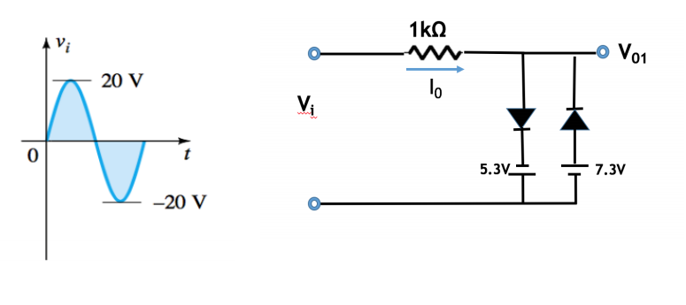

Transcribed Image Text:1kO
1 Vi
-o Vo1
20 V
lo
Vi
5.3V_
7.3V
-20 V
Expert Solution
This question has been solved!
Explore an expertly crafted, step-by-step solution for a thorough understanding of key concepts.

Step by stepSolved in 3 steps with 2 images

Knowledge Booster


Learn more about
Need a deep-dive on the concept behind this application? Look no further. Learn more about this topic, electrical-engineering and related others by exploring similar questions and additional content below.Similar questions
- 4. Assume the Blue LED has a forward turn on voltage of 4 V and exhibits ideal diode behavior. For the circuit below, sketch the voltage across the diode and the voltage across the resistor (versus time) for the following Vin values. On your waveforms, indicate the time periods when the LED is on. a. Vin= 3 sin(2π *60t) V b. Vin = 5 sin(2π *60t) V Blue LED # Vin 1k R2arrow_forwardPlease help with the below zener diode questionarrow_forwardPlease Help ASAP!!! Solve using option Carrow_forward
- Determine the output voltage V out of the circuit shown in Figure. However, when the Zener diode is forward biased, the voltage of both ends is approximated to 0.7V.arrow_forwardThe four diodes used in a bridge rectifier circuit have forward resistances which may be considered constant at 1 ohm and infinite reverse resistance. The alternating supply voltage is 220 V r.m.s. and load resistance is 580 ohm. Calculate (i) mean load current and (ii) power dissipated in each diode.arrow_forwardNote: The diode is silicone. Complete explanation please thank youarrow_forward
arrow_back_ios
arrow_forward_ios
Recommended textbooks for you
- Introductory Circuit Analysis (13th Edition)Electrical EngineeringISBN:9780133923605Author:Robert L. BoylestadPublisher:PEARSON
 Delmar's Standard Textbook Of ElectricityElectrical EngineeringISBN:9781337900348Author:Stephen L. HermanPublisher:Cengage Learning
 Programmable Logic ControllersElectrical EngineeringISBN:9780073373843Author:Frank D. PetruzellaPublisher:McGraw-Hill Education
  Fundamentals of Electric CircuitsElectrical EngineeringISBN:9780078028229Author:Charles K Alexander, Matthew SadikuPublisher:McGraw-Hill Education
 Electric Circuits. (11th Edition)Electrical EngineeringISBN:9780134746968Author:James W. Nilsson, Susan RiedelPublisher:PEARSON
 Engineering ElectromagneticsElectrical EngineeringISBN:9780078028151Author:Hayt, William H. (william Hart), Jr, BUCK, John A.Publisher:Mcgraw-hill Education,
Introductory Circuit Analysis (13th Edition)
Electrical Engineering
ISBN:9780133923605
Author:Robert L. Boylestad
Publisher:PEARSON
Delmar's Standard Textbook Of Electricity
Electrical Engineering
ISBN:9781337900348
Author:Stephen L. Herman
Publisher:Cengage Learning
Programmable Logic Controllers
Electrical Engineering
ISBN:9780073373843
Author:Frank D. Petruzella
Publisher:McGraw-Hill Education
Fundamentals of Electric Circuits
Electrical Engineering
ISBN:9780078028229
Author:Charles K Alexander, Matthew Sadiku
Publisher:McGraw-Hill Education
Electric Circuits. (11th Edition)
Electrical Engineering
ISBN:9780134746968
Author:James W. Nilsson, Susan Riedel
Publisher:PEARSON
Engineering Electromagnetics
Electrical Engineering
ISBN:9780078028151
Author:Hayt, William H. (william Hart), Jr, BUCK, John A.
Publisher:Mcgraw-hill Education,