12 V 오3V Q2 8.3 A (a) 12 V 3 V lo2 los Os Q2 A. 5 A 8.3 A (b)


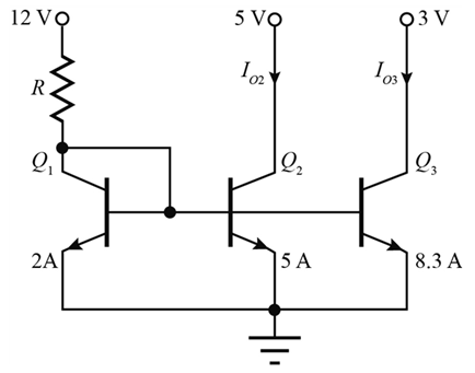
(a) What are the output currents in the circuit shown in P16.16 (a)if the area of transistor Q1 is changed to 2A, and R = 60 kΩ? Use βFO = 120 and VA =75 V. (b) Repeat for P16.16(b).


Given:
(a) What are the output currents in the circuit shown in P16.16 (a)if the area of transistor Q1 is changed to 2A, and R = 60 kΩ? Use βFO = 120 and VA =75 V. (b) Repeat for P16.16(b).
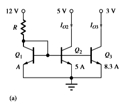
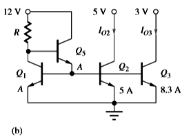
The BJT current mirror circuit as following below,
a)
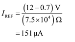
To find the reference current as shown below,
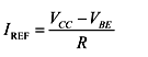
Substituting the values as shown below,
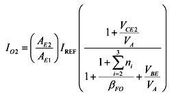
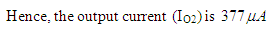
To find the output current (IO2) as shown below,
The summation as shown below,
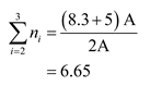
Substituting the values as shown below,
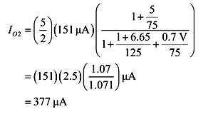
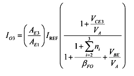
To find the output current (IO3) as shown below,
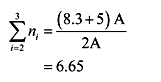
The summation as shown below,
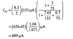
Substituting the values as shown below,

Step by step
Solved in 9 steps with 24 images


